Clutch mechanism with moveable injector retainer wall for door lock system

Inactive Publication Date: 2001-09-11
HARROW PRODS
View PDF15 Cites 174 Cited by
  • Summary
  • Abstract
  • Description
  • Claims
  • Application Information

AI Technical Summary

Benefits of technology

Another object of the invention is to provide a new and improved clutch mechanism which is capable of efficient and reliable operation under the increased torque demands and various conditions that may be applied to lever handle type actuators.
A further object of the inventio

Problems solved by technology

The recent hardware trends and the Americans with Disabilities Act regulatory requirements for lever handles at both the exterior and interior sides of the door have made some conventional latch/lock set mechanisms vulnerable to mechanical failure.
Application of an opening force to lever handles may result in significant larger moments be

Method used


Image

  • Clutch mechanism with moveable injector retainer wall for door lock system
  • Clutch mechanism with moveable injector retainer wall for door lock system
  • Clutch mechanism with moveable injector retainer wall for door lock system

Examples


Example

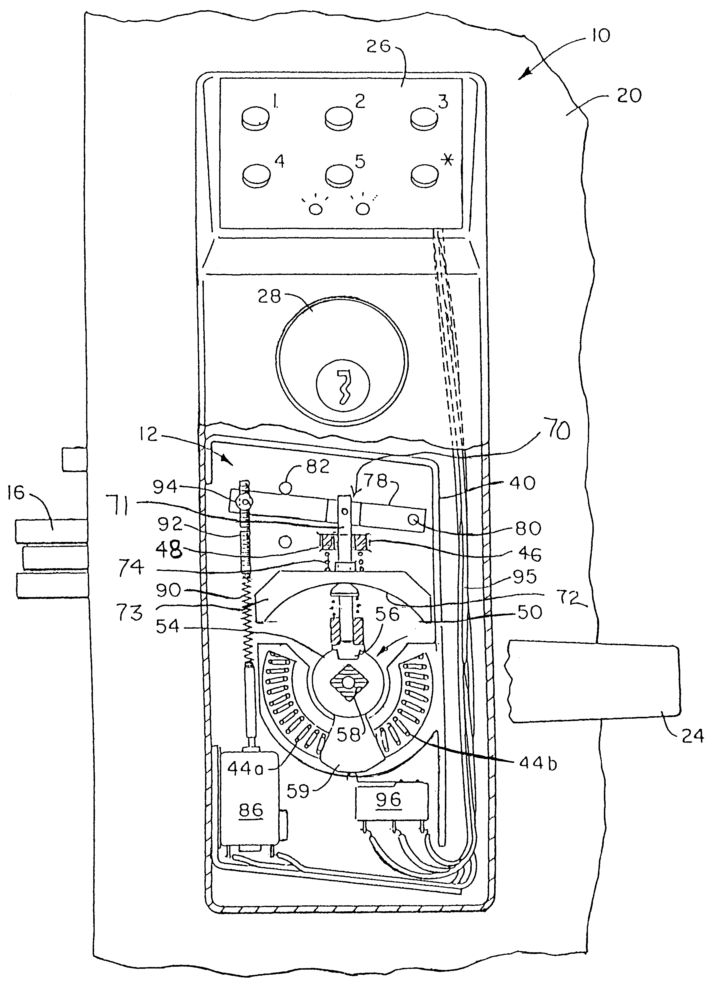
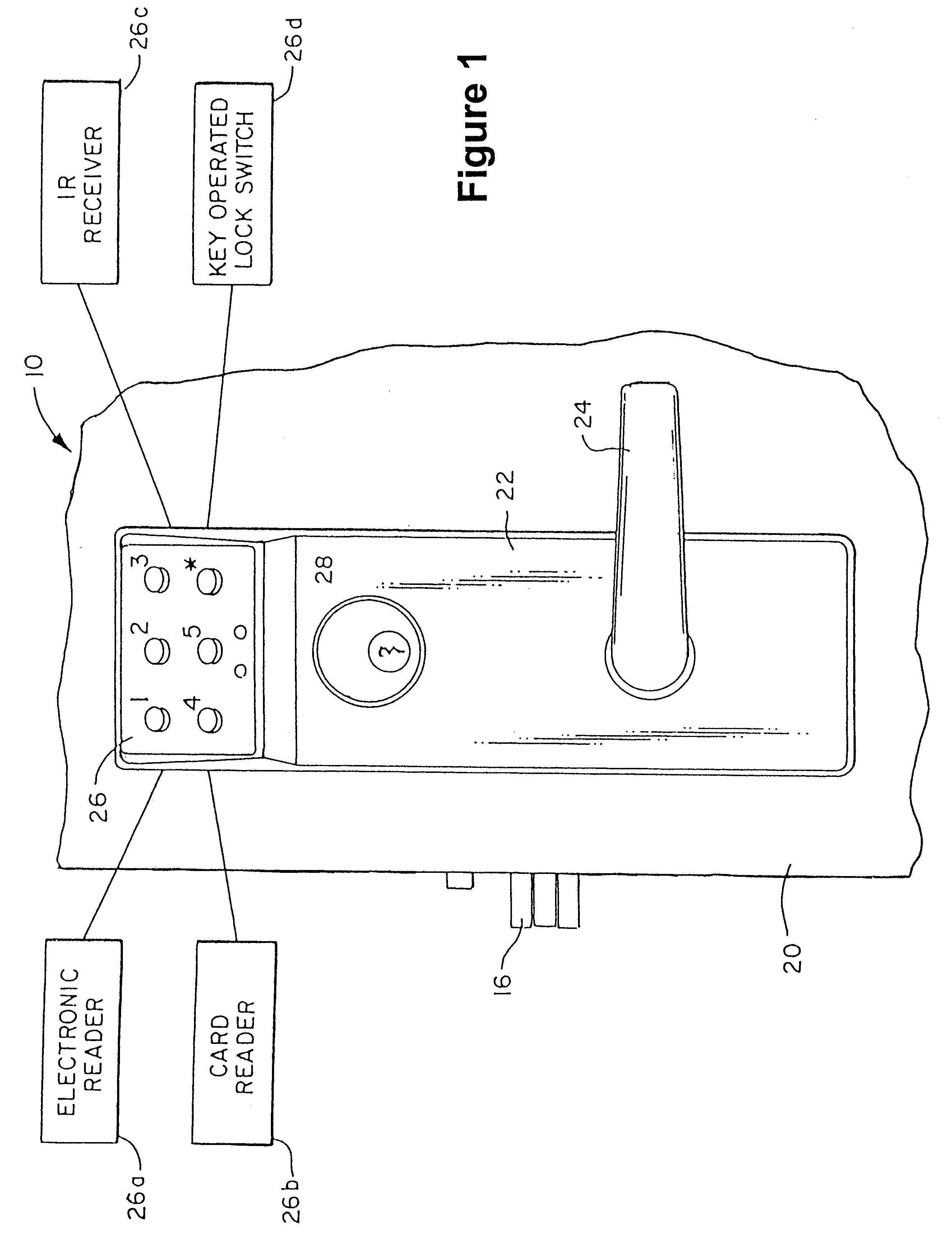
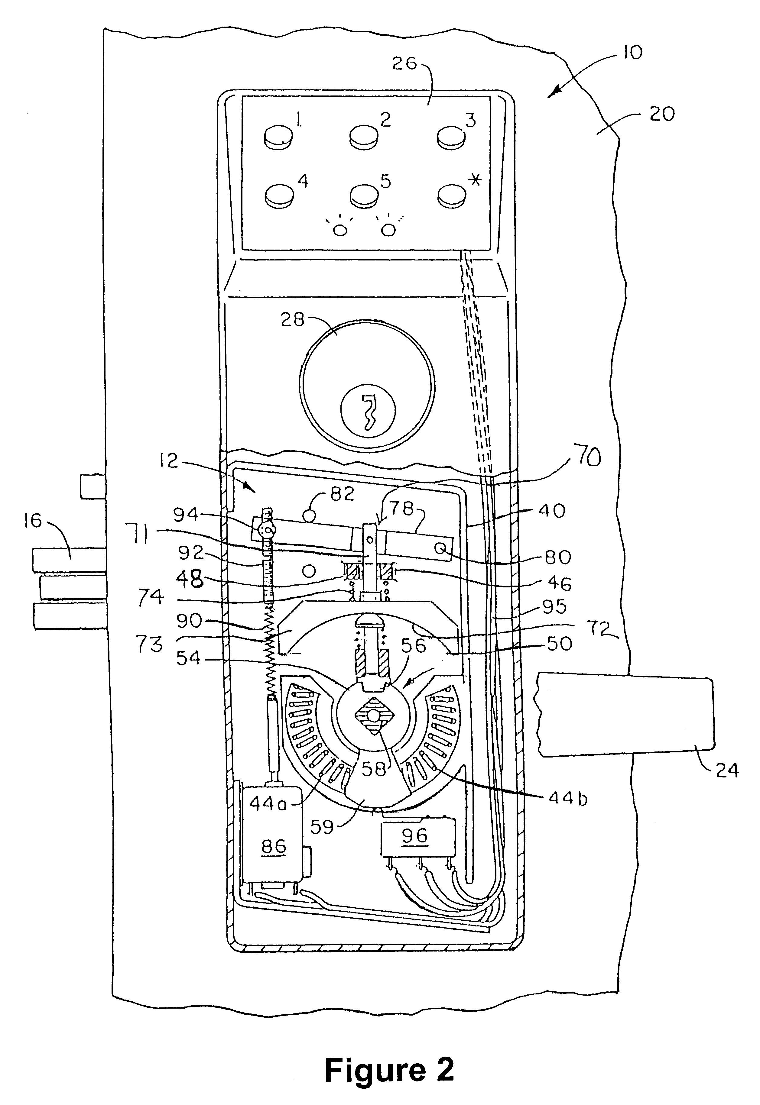
With reference to the drawings wherein like numerals represent like parts throughout the several figures, a door lock system 10 incorporates a clutch mechanism 12 in accordance with the present invention. The lock system includes a lockset 14 which may be a mortise type lockset or other type lockset. The lockset implements a latching function via latch 16 for latching and locking the door 20. Except for the modifications described herein, the lockset may be of any conventional form and function and is of a type wherein the outside operator or handle retracts the latch. The lockset 14 is preferably operated by a cam or actuator arm which interacts with a spindle or spindles rotatably connectable with lever handles at each side of the door for withdrawing the latch.

In an illustrated embodiment, the door lock system employs a frontal escutcheon 22 which is mounted to the exterior side of the door 20. A lever handle 24, which is normally in a generally horizontal position, at the exteri...


PUM


Abstract

A door lock system includes a clutch mechanism for a lockset and has particular applicability in conjunction with lever handles. Two coupling assemblies are selectively rotatably coupled by a coupling pin. One coupling assembly is rotatably coupled to the lockset actuator. The other coupling assembly is rotatably coupled to the exterior door handle. A drive assembly includes a motor and employs an injector which has a movable arcuate shoulder and which selectively controls the position of the coupling pin to provide for the locking and unlocking functions.

Description

BACKGROUND OF THE INVENTIONThis invention relates generally to security systems which are mounted to a door to provide a latching and locking function. More particularly, the present invention relates generally to lock devices which may be employed with entry control devices to control access through a door.Locksets which incorporate a lockable latch and / or a dead bolt have long been incorporated into doors. A number of door mounted security systems which employ electronic input such as key pads, contact activatable chips, card readers and other electronic means have also been employed for use in conjunction with the mechanical latching and locking mechanisms.The recent hardware trends and the Americans with Disabilities Act regulatory requirements for lever handles at both the exterior and interior sides of the door have made some conventional latch / lock set mechanisms vulnerable to mechanical failure. Application of an opening force to lever handles may result in significant large...

Claims


Application Information

Patent Timeline
IPC IPC(8): E05B47/06
CPCE05B47/0692Y10S292/27E05B2047/0031Y10T70/5416Y10T70/5496Y10T70/5677Y10T70/5805Y10T70/7062
Inventor FROLOV, GEORGE
Owner HARROW PRODS
Why Eureka
Try Eureka