
Filtration and cleaning system for sprinkler irrigation drop nozzles

a technology of filtration and cleaning system and sprinkler irrigation, which is applied in the direction of lighting and heating apparatus, combustion types, separation processes, etc., can solve the problems of clogging orifices, uneven water application on the field, and none of the above-ground water systems are suitable for use on overhead sprinkler irrigation systems, etc., to eliminate constant maintenance and servicing, and simple and durable construction

Active Publication Date: 2014-12-30
AMERICAN AGRI PRODS
View PDF30 Cites 0 Cited by
  • Summary
  • Abstract
  • Description
  • Claims
  • Application Information

AI Technical Summary

Benefits of technology

The patent describes an irrigation system that has a filter to catch debris. The system uses a plunger to flush the filter and keep it clean. The plunger is designed to be easily released and can seal off the debris outlet. The system has a screen and a spray nozzle to catch the debris and a purging mechanism to keep the filter clean. The system is reliable, durable, and cost-effective.

Problems solved by technology

Typically, the water carries dirt, rust, and other debris which clog the orifices of the spray nozzles.
Such clogging results in uneven water application on the field.
This problem necessitates cleaning the clogged orifices by the user of the irrigation system.
While the prior art is replete with designs for self-cleaning shower heads, self-cleaning filters, and the like, none are entirely suitable for use on overhead sprinkler irrigation systems.
Therefore, they are not compatible with the nozzles already in use on the systems.
Additionally, there is no provision for storage of accumulated debris.
Moreover, the prior art devices do not allow for passage of the larger particles of debris.
While the filtering device shown in U.S. Pat. No. 4,064,046, allows for connection to different nozzles and for storage of accumulated debris, the need to visually check and manually service it makes it undesirable.
Further, the size and configuration of this device makes it impractical for use on an overhead sprinkler irrigation system.

Method used


Image

  • Filtration and cleaning system for sprinkler irrigation drop nozzles
  • Filtration and cleaning system for sprinkler irrigation drop nozzles
  • Filtration and cleaning system for sprinkler irrigation drop nozzles

Examples


Embodiment Construction

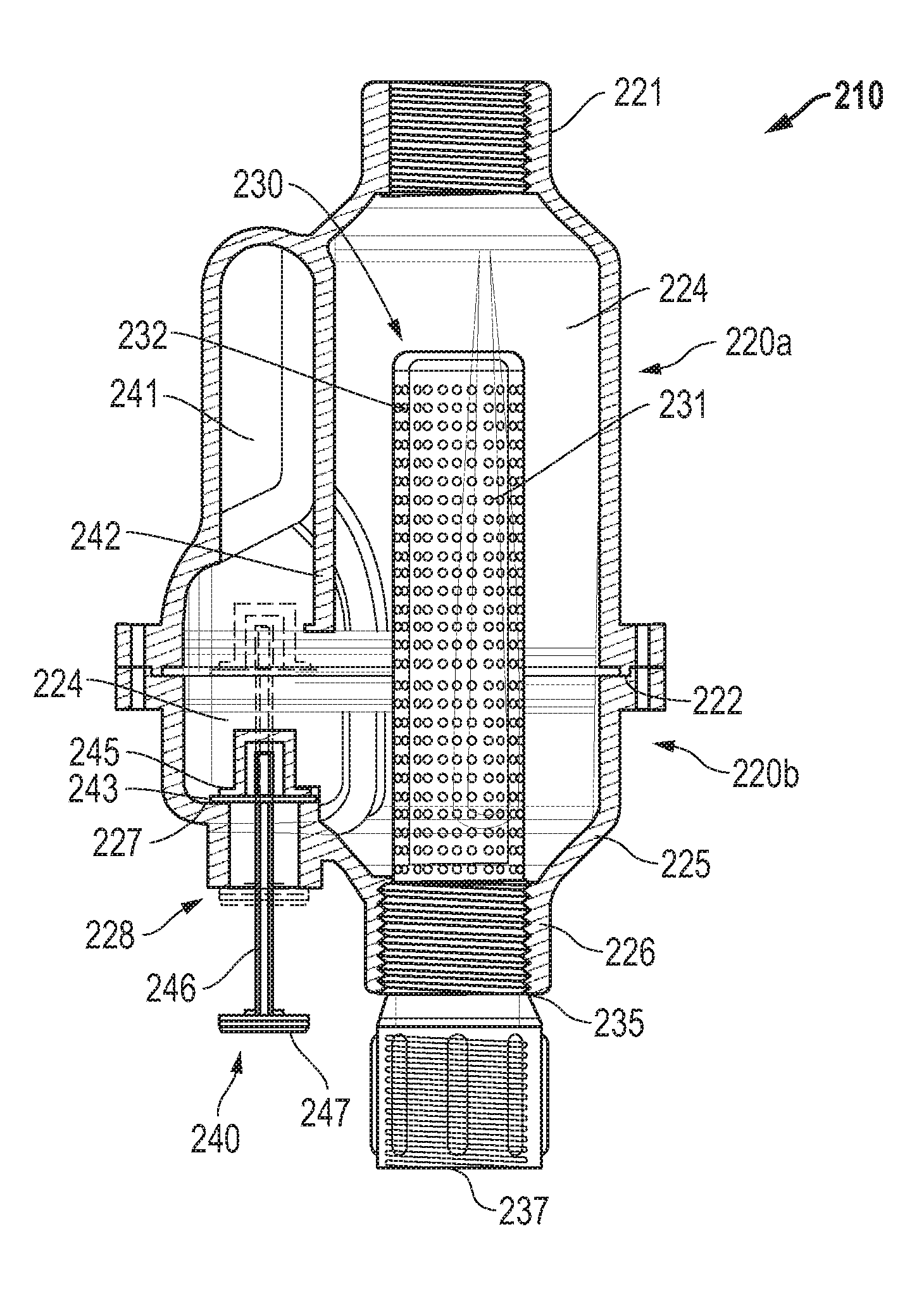
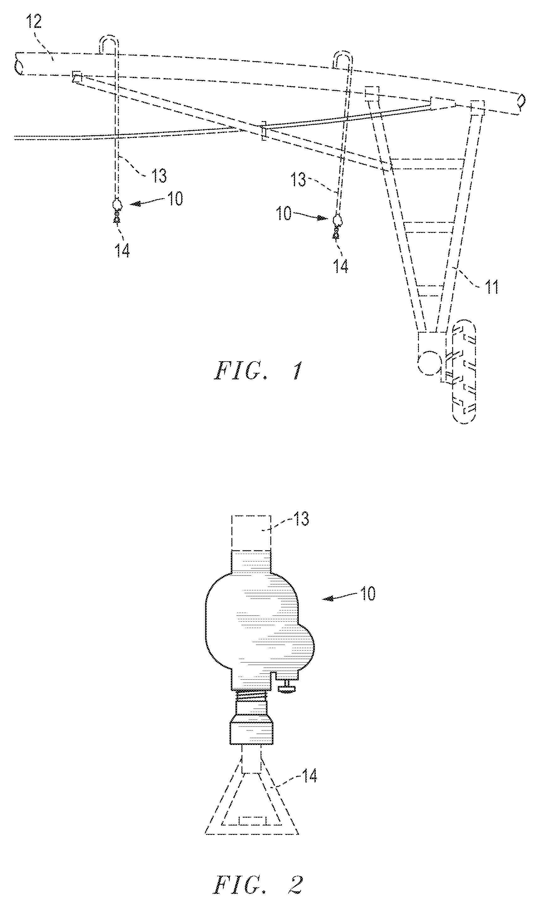
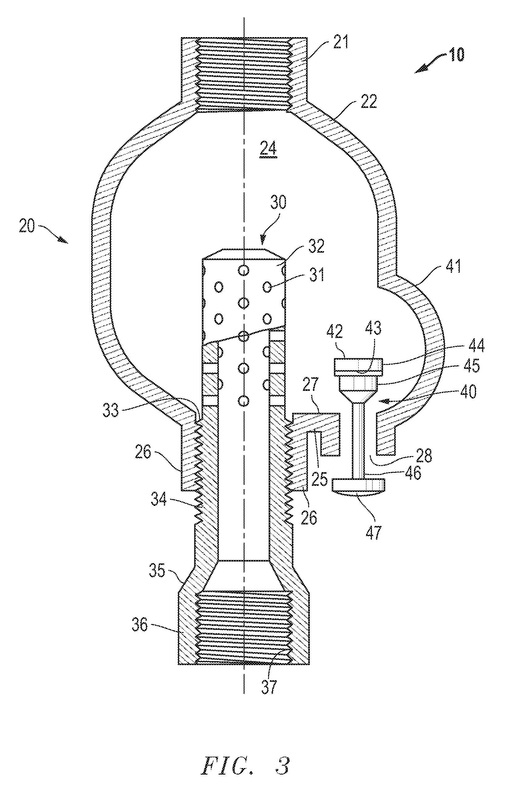
[0022]Referring to FIGS. 1-3, one embodiment of the invention includes a filter 10 in one type of contemplated environment. Specifically, the filter 10 is shown installed on a section of an overhead sprinkler irrigation system including a drive unit 11, span pipe 12, and drop pipe 13. A conventional irrigation drop spray nozzle 14, such as those known in the art, is attached to the filter 10. When the irrigation system is in use, water is pumped from one end of the system to the other through the span pipe 12, through the drop pipes 13, the filters 10, and the spray nozzles 14 for irrigating crops and the like.

[0023]Referring now to FIG. 3, one embodiment of the invention comprises a hollow, generally cylindrical body 20. At the upper end of the body 20, a neck portion or inlet 21 is provided having female threads thereon to facilitate connection to the drop pipe 13 (see FIGS. 1 and 2). The lower end of the body 20 includes two openings, including a debris outlet 28 and a coupling p...


PUM

PropertyMeasurementUnit
pressureaaaaaaaaaa
axial lengthaaaaaaaaaa
diameteraaaaaaaaaa

Abstract

A filter for use with overhead sprinkler irrigation systems is disclosed. The filter includes a body, a removable screen, and a manually-actuated plunger adjacent the screen. A water hammer table is partitioned in the body and located above the plunger. The plunger is positioned for reciprocal movement through a debris outlet between an open, debris-discharging position, and a closed filtering position. The plunger defaults to the closed filtering position by pressurized water flowing through the body. The water is simultaneously filtered through the screen and passes out a clean water outlet while debris accumulates within the body. The plunger may be manually retracted to the open, debris-discharging position at any time, whereby accumulated debris is flushed out of the body through the debris outlet by residual water flowing therethrough.

Description

[0001]This application claims priority to and the benefit of U.S. Provisional Patent App. No. 60 / 745,069, filed on Apr. 18, 2006, and also incorporates U.S. Pat. No. 5,087,355 by reference. This application is a continuation-in-part of and claims priority from U.S. patent application Ser. No. 11 / 697,781, filed on Apr. 9, 2007, which application is incorporated by reference herein in its entirety.BACKGROUND OF THE INVENTION[0002]1. Technical Field[0003]The present invention relates in general to water filtration and, in particular, to an improved system, method, and apparatus for filtering water dispensed by sprinkler irrigation systems and purging the filtration system.[0004]2. Description of the Related Art[0005]Sprinkler irrigation systems typically pump water from wells, rivers, lakes, and other open bodies of water. Typically, the water carries dirt, rust, and other debris which clog the orifices of the spray nozzles. Such clogging results in uneven water application on the fiel...

Claims


Application Information

Patent Timeline
Patent Type & Authority Patents(United States)
IPC IPC(8): B05B15/00A01G25/09B05B1/20A62C35/68A01G25/02B05B3/18B05B1/14B05B15/02
CPCA62C35/68B05B15/008A01G25/023B05B15/0208B05B1/20A01G25/092B05B3/18B05B15/40B05B15/52Y02A40/22
Inventor BEER, GERALDFREITAS, MICHAEL WOODFORD
Owner AMERICAN AGRI PRODS
Learn More