Roller mechanism for multiple directions control

a technology of multiple directions and rollers, applied in the direction of mechanical control devices, manual control with single controlling members, instruments, etc., can solve the problems of a relatively expensive mechanism for the input device with the light emitter and receiver within the roller, a difficult use of the laterally movable roller, and a simplified structure with a short life span. , to achieve the effect of simple and durable structur

Inactive Publication Date: 2007-05-03
KYE SYST CORP
View PDF9 Cites 6 Cited by
  • Summary
  • Abstract
  • Description
  • Claims
  • Application Information

AI Technical Summary

Benefits of technology

[0007] It is accordingly an object of the present invention to provide a roller mechanism with a simple and durable structure, and that may be used for scrolling an image on a computer display in multiple directions.
[0008] It is another object of the present invention to provide a roller mechanism suitable for scrolling an image on a computer display in multiple directions, with a lower cost in production.
[0009] It is yet another object of the present invention to provide a roller mechanism suitable for scrolling an image on a computer display in multiple directions, and which is easy for a user to operate.

Problems solved by technology

However, this arrangement suffers the disadvantage that the laterally movable roller is difficult to use, prompting a further improvement described in U.S. Patent Publication No. 2003 / 0025673.
While more convenient to use, the input device with the light emitter and receiver within the roller is a relatively costly mechanism, particularly when the input device in which it is used is miniaturized.
However, due to the tight narrow tolerance of the combination, the simplified structure has a short life span if the user tilts the roller frequently.

Method used


Image

  • Roller mechanism for multiple directions control
  • Roller mechanism for multiple directions control
  • Roller mechanism for multiple directions control

Examples


Embodiment Construction

[0019] The following detailed description is of the best presently contemplated modes of carrying out the invention. This description is not to be taken in a limiting sense, but is made merely for the purpose of illustrating general principles of embodiments of the invention. The scope of the invention is best defined by the appended claims.

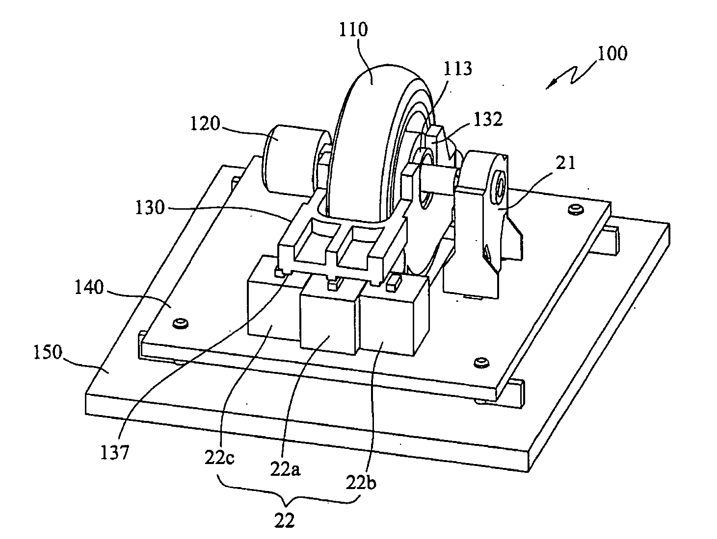
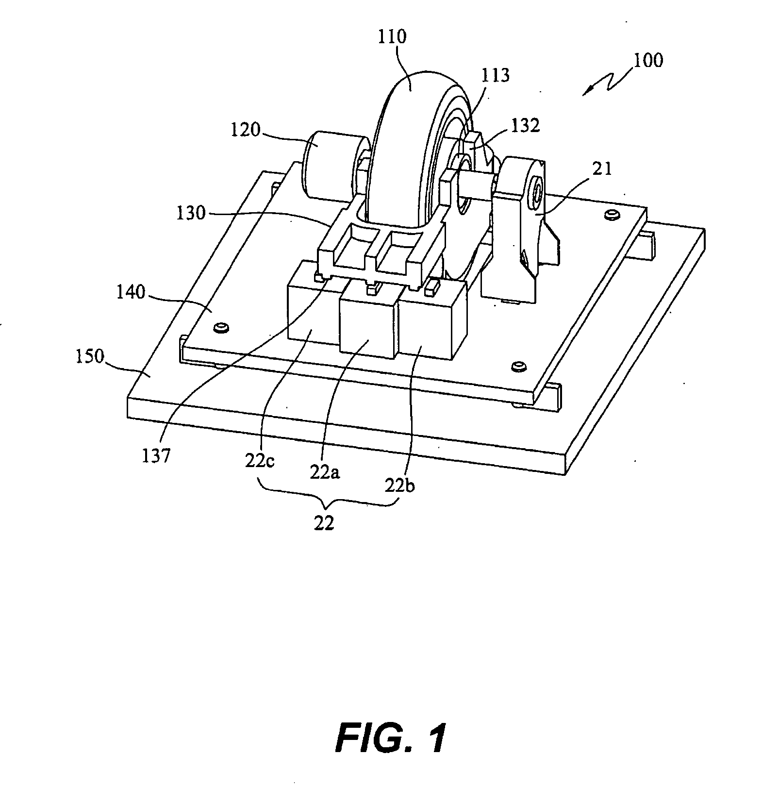
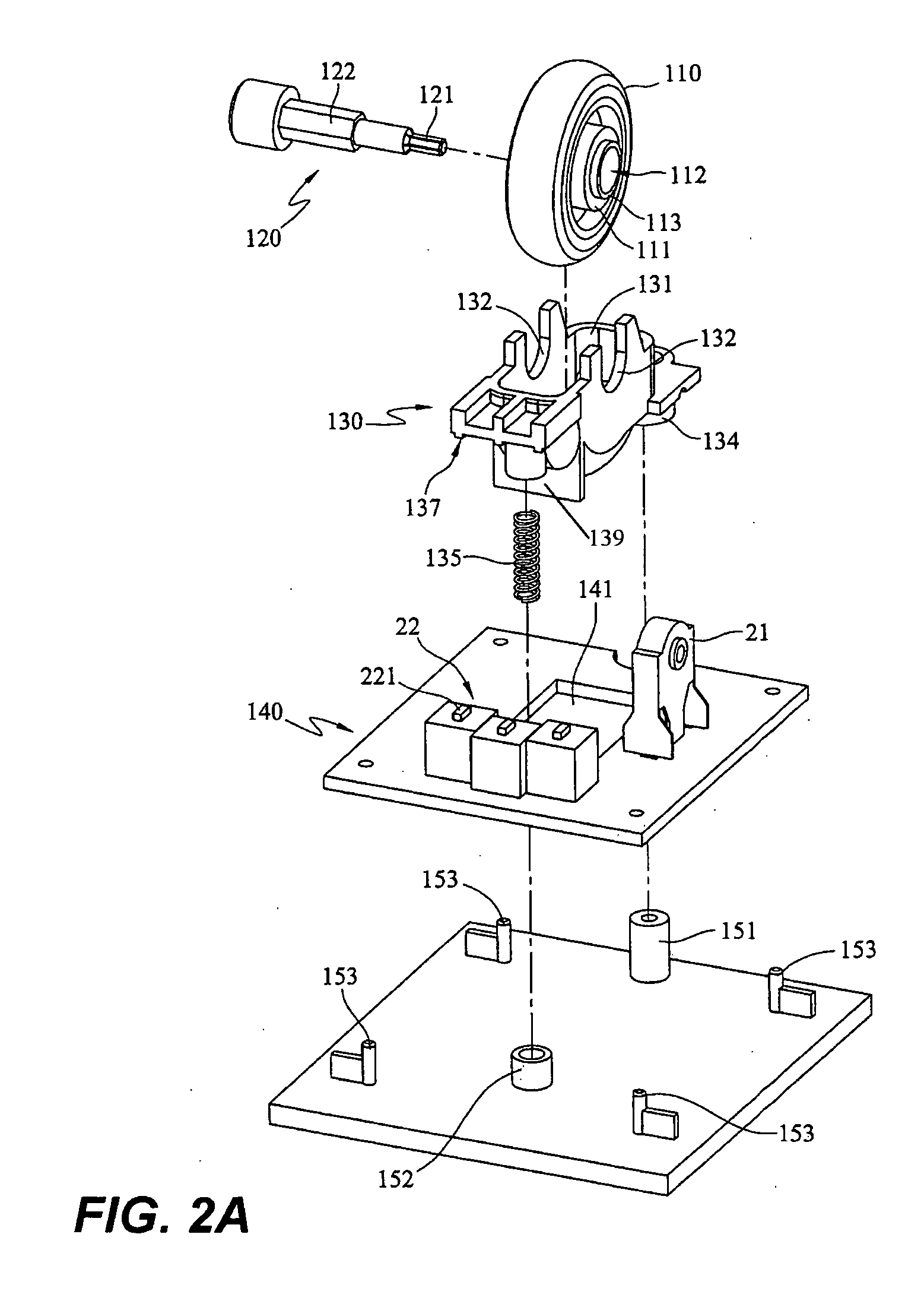
[0020] Referring to FIG. 1, 2A and 2B, the roller mechanism 100 comprises a carriage 130, and a roller 110 with a shaft 120 which is rotatable within the carriage 130. Each side of the roller 110 has a flange 113 such that he roller 110 is mounted in the pair of recesses 132. Each side of the roller 110 further has an inner portion 111 that fits between the pair of recesses 132. The carriage 120 has a coupling portion 134, which is further pivoted to a post 151 of a bottom 150.

[0021] Referring to FIG. 2A, the shaft 120 has a smaller hexagonal portion 121 for coupling to an encoding unit 21, and a larger hexagonal portion 122 for penetrating the...


PUM


Abstract

The present invention relates to a roller mechanism for generating a plurality of control signals, for example to scroll an image on a computer display in multiple directions. The roller mechanism has a carriage, and a roller rotatable within the carrier. The roller can drive an encoding unit to output the control signal. The carriage has a coupling portion, and the coupling portion is pivoted to a bottom support. Thus the roller and the carriage are turnable relative to the coupling portion in a fan-shaped movement while the roller is also being rotated within the carriage.

Description

BACKGROUND OF THE INVENTION [0001] 1. Field of the Invention [0002] The present invention relates to a roller mechanism for generating a plurality of control signals. The control signals may be used for scrolling an image on a computer display in multiple directions. [0003] 2. Description of the Prior Art [0004] GUI (graphical user interface) controls have been widely applied to a variety of devices, including computers, telephones, televisions, hand-held devices or the like. For example, U.S. Pat. No. 5,530,455 discloses a pioneering utilization of a roller in a computer input device for scrolling an image on a computer display either in a horizontal and vertical direction. However the scrolling direction is limited to a one specified direction at a time, or the cursor has to be moved to the other scrolling bar such that the computer will verify a desired scrolling direction. [0005] In order to overcome the inconvenience mentioned above, U.S. Pat. No. 6,700,564 discloses a laterall...

Claims


Application Information

Patent Timeline
Patent Type & Authority Applications(United States)
IPC IPC(8): G09G5/08
CPCG06F3/0362G05G9/047
Inventor WANG, WEI-CHUAN
Owner KYE SYST CORP
Why Eureka
Try Eureka