Planter dual wheel mounting device

Inactive Publication Date: 2013-09-12
LEADING EDGE INDS
View PDF11 Cites 5 Cited by
  • Summary
  • Abstract
  • Description
  • Claims
  • Application Information

AI Technical Summary

Benefits of technology

[0005]The present invention comprises an auxiliary wheel adapter system with the mounting of an auxiliary wheel in coaxial alignment with the existing wheel and at a disposition closely spaced laterally of the exis

Problems solved by technology

When using the prior art planters, the single wheels commonly cause excessive soil comp

Method used


Image

  • Planter dual wheel mounting device
  • Planter dual wheel mounting device
  • Planter dual wheel mounting device

Examples


Embodiment Construction

[0015]The present invention and the various features and advantageous details thereof are explained more fully with reference to the non-limiting embodiments described in the following description.

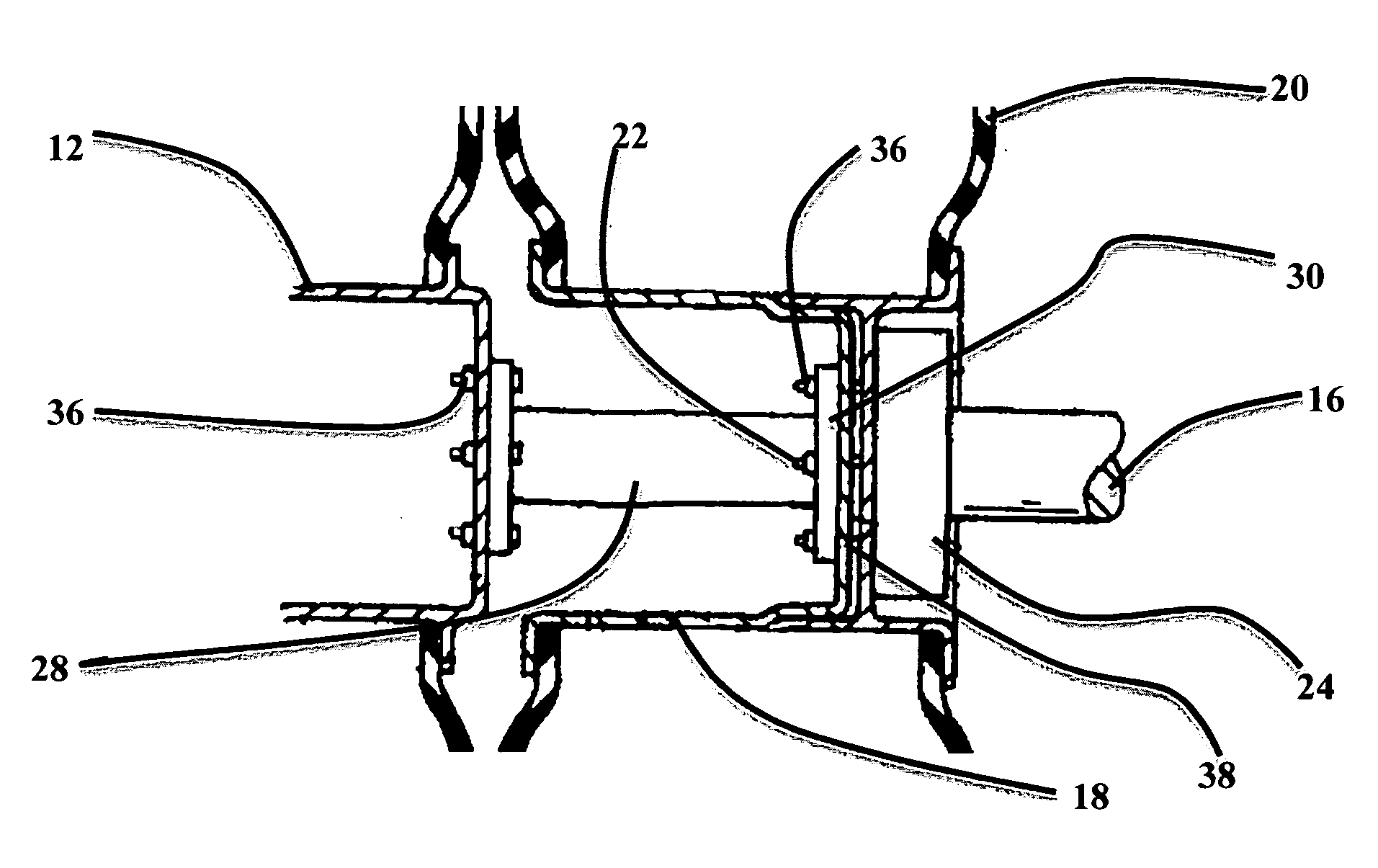
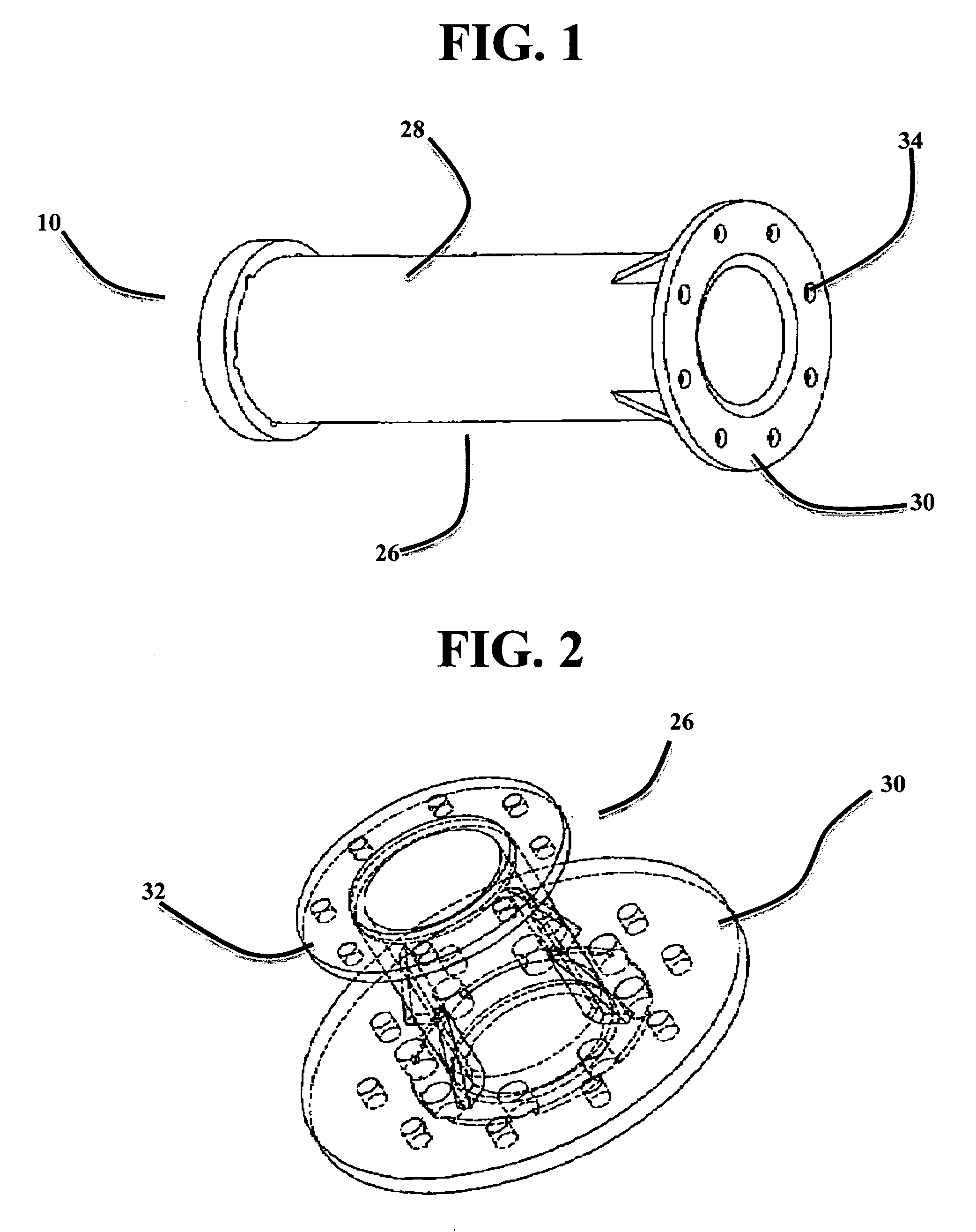
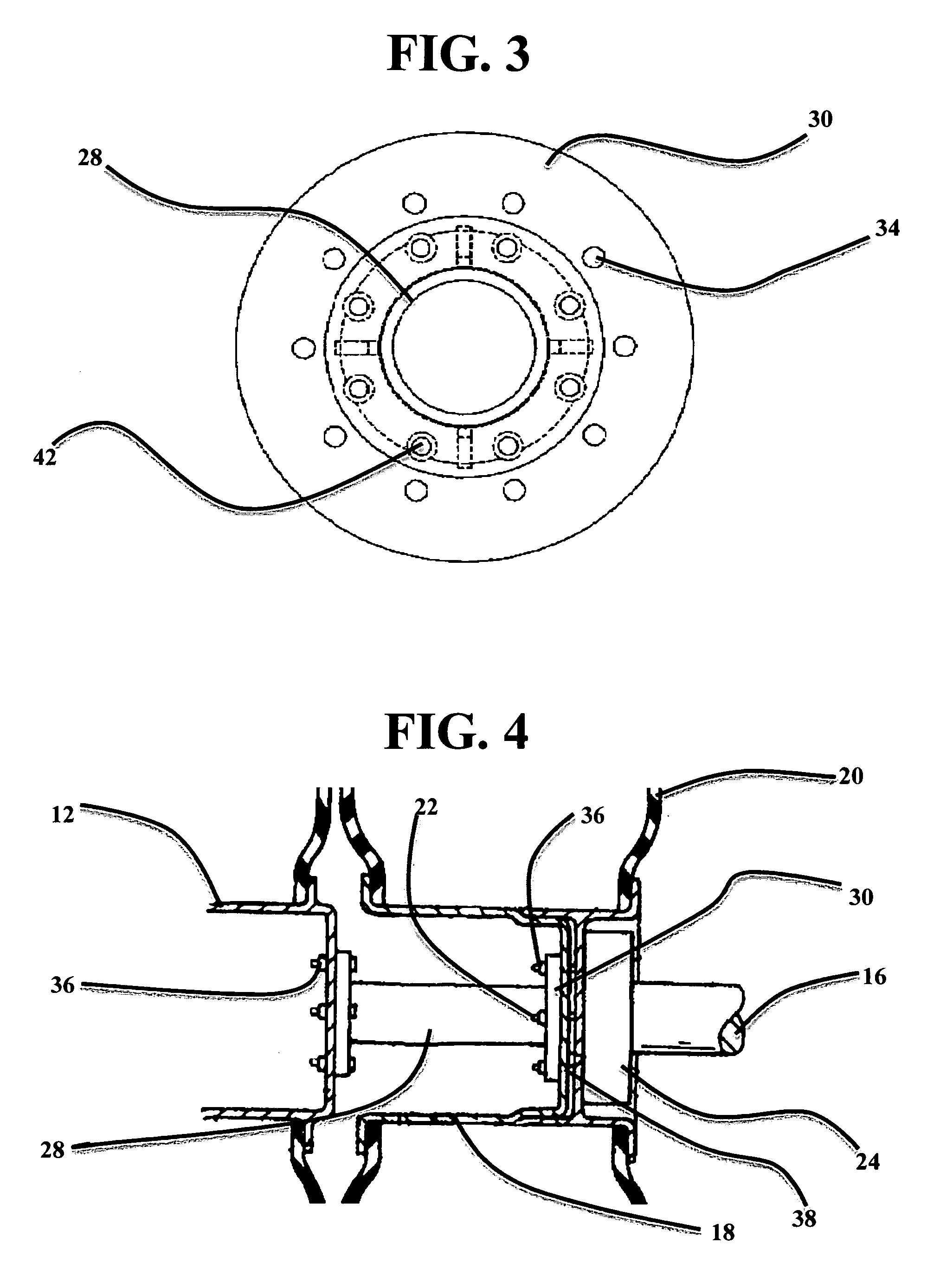
[0016]FIGS. 1 through 6 show a device of the present invention which allows for attaching dual wheels to an agricultural planter. The adaptor means of the present invention is indicated by numeral 10 and will be described in conjunction with the auxiliary planter wheels 12 and the OEM planter wheels 14 supported on the planter axles 16. The OEM planter wheels 14 include inboard steel rim structures 18 concentrically fitted respectively with surface engaging tire structures 20. A plurality of bolt apertures 38 arranged in a circular pattern (not shown) to match the pattern of the wheel mounting studs 22. The mounting studs 22 are inserted through the bolt apertures 38 of the OEM rim structure 18. Wheel nuts 36 are threaded onto the mounting studs 22 to secure the OEM planter wheel 14 to the...


PUM


Abstract

A device for mounting an additional wheel on an agricultural planter to provide a dual wheel assembly. Said device comprising a generally cylindrical member with radially projecting flanged portions at each end thereof, a plurality of apertures extending through the flanged portion at one end of said cylindrical member and positioned to receive the wheel mounting studs of a planter's wheel hub, and a plurality of externally threaded shafts projecting outwardly from the flanged portion at the opposite end of said cylindrical member and positioned to mate with the mounting apertures of the auxiliary planter wheel being added.

Description

BACKGROUND OF THE INVENTION[0001]1. Field of the Invention[0002]The present invention relates to a hub extension for attaching dual wheels to an agricultural planter and in particular to a hub extension for use on Bauer-John Deere and Case IH planters.[0003]2. Description of the Related Art[0004]A planter is an agricultural farm implement towed behind a tractor, used for sowing crops through a field. The planter is connected to the tractor with a draw-bar, or a three-point hitch. Planters lay the seed down in precise manner along rows. Seeds are distributed through devices called row units. The row units are spaced evenly along the planter. Planters vary greatly in size, from 2 rows to 48, with the largest being the 48-row John Deere DB120. Prior art planters typically included one or more axles containing a single wheel at each end of the axle. When using the prior art planters, the single wheels commonly cause excessive soil compaction, lack traction during wet conditions and caus...

Claims


Application Information

Patent Timeline
IPC IPC(8): B60B11/00
CPCB60B11/02B60B11/00
Inventor GENGERKE, SHAWN
Owner LEADING EDGE INDS
Why Eureka
Try Eureka