
Automatic Dye-Meter

Active Publication Date: 2014-01-02
STAN ENG CORP
View PDF13 Cites 3 Cited by
  • Summary
  • Abstract
  • Description
  • Claims
  • Application Information

AI Technical Summary

Benefits of technology

The present invention introduces an automatic dye-meter that solves the problem of manually mixing dye components from commercial bottles. Instead, it allows for quicker and more efficient purging of dyeing compounds for painting vehicles. Overall, this device simplifies and streamlines the process of preparing dyeing components, making it easier to prepare and use in real-life scenarios.

Problems solved by technology

However, a current technical trend nowadays is marketing the dyeing components, especially in the particular sector of motor vehicle body, inside plastic bottles that must be stored inside special thermostatic cabinets and do not require any more a continuous stirring of the component inside them: currently, however, there are no specific dye-meters that allow the automatic batching of individual dyeing components directly from their commercial bottles.
Obviously, above all in case of particularly complex dyeing compounds, the execution of the above described operations for every single bottle of dyeing component requires a long interval of time.
Moreover, the completely manual execution of such operations, above all those pertaining to the selection of the individual bottles and the weighing of the batches of individual components, can often be subjected to human errors that, taking into account the non-neglected cost of the affected paints, have a negative outcome on the economy of such operations.

Method used


Image

  • Automatic Dye-Meter
  • Automatic Dye-Meter
  • Automatic Dye-Meter

Examples


Embodiment Construction

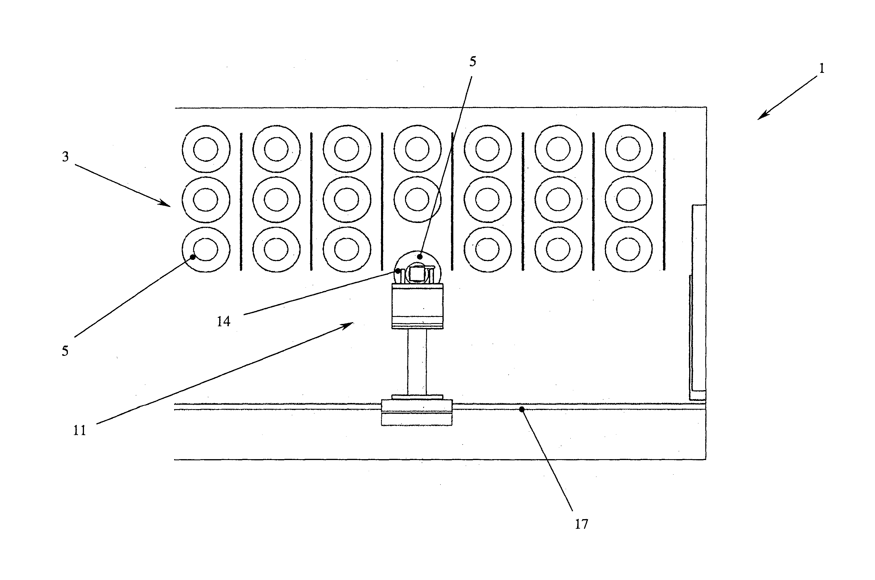
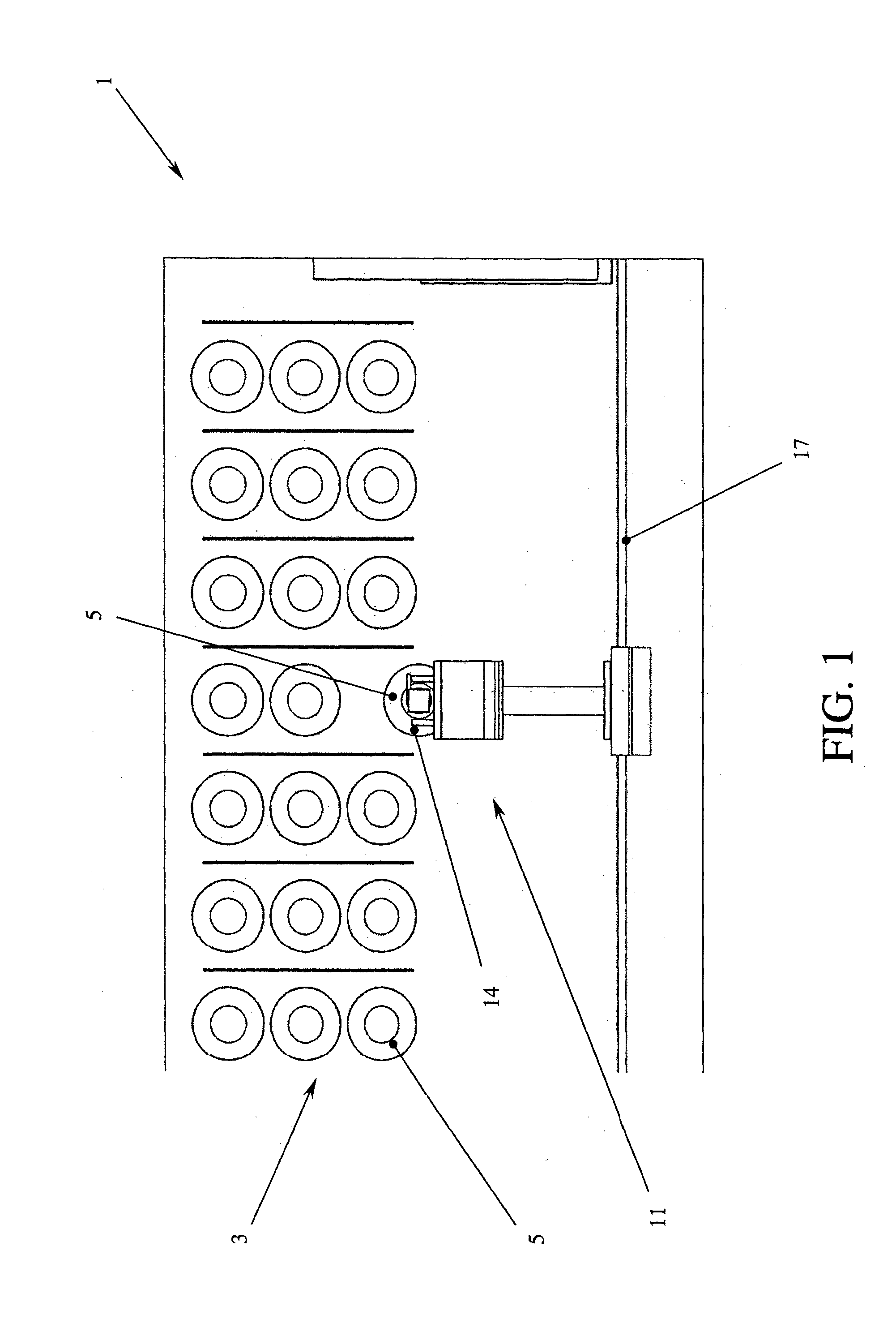
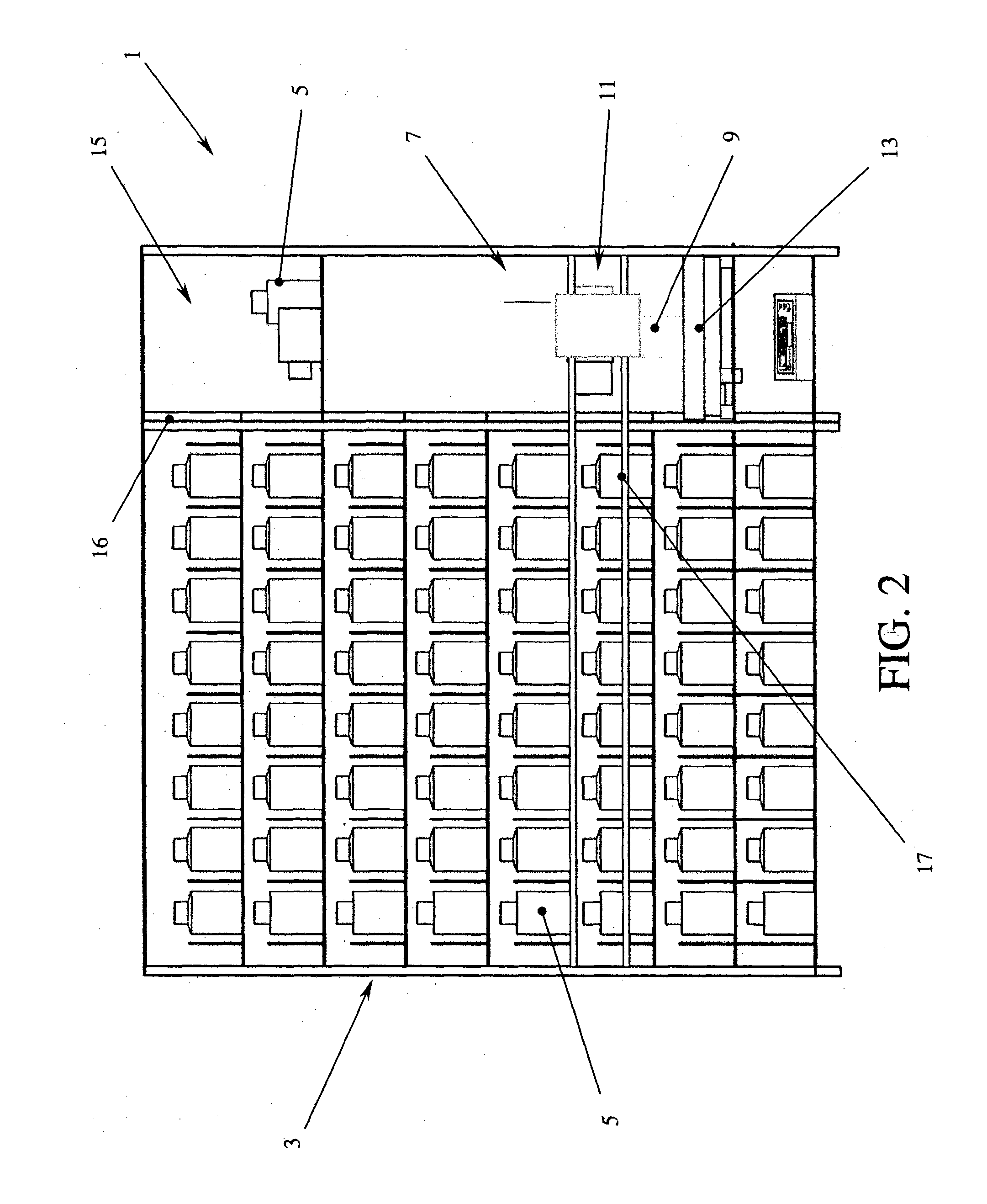
[0013]With reference to the Figures, it is possible to note that the automatic dye-meter 1 according to the present invention is composed of at least one first compartment 3 for stocking and storing a plurality of bottles 5 containing dyeing components, each one of which is equipped with at least one plug equipped with pumping means for such component, such bottles 5 being arranged inside such first compartment 3 according to a known order, at least one second compartment 7 for batching such components from such bottles 5 for preparing a final dyeing compound inside at least one mixing container 9 arranged inside such second compartment 7, handling means 11 adapted to take at least one of such bottles 5 from such first compartment 3 (FIG. 1), transporting such bottle 5 from such first compartment 3 to such second compartment 7 (FIGS. 2 and 3), possibly in the meantime stirring such bottle 5, suitably inclining such bottle 5, actuating such pumping means to allow pouring and batching...


PUM

PropertyMeasurementUnit
Timeaaaaaaaaaa
Weightaaaaaaaaaa

Abstract

An automatic dye-meter (1) is described, composed of at least one first compartment (3) for stocking and storing a plurality of bottles (5) containing the dyeing components, each one of such bottles (5) being equipped with at least one plug equipped with pumping means for such component, such bottles (5) being arranged inside such first compartment (3) according to a known order, at least one second compartment (7) for batching such components from such bottles (5) to obtain a final dyeing compound inside at least one mixing container (9) arranged inside such second compartment (7), handling means (11) adapted to take at least one of such bottles (5) from such first compartment (3), transport such bottle (5) from such first compartment (3) to such second compartment (7), incline such bottle (5), actuate such pumping means to allow pouring and batching such component inside such mixing container (9), and take back such bottle (5) inside such first compartment (3).

Description

BACKGROUND ART[0001]The present, invention refers to an automatic dye-meter.BACKGROUND OF THE INVENTION[0002]As known, dye-meters are batching machines for preparing dyeing composites, such as paints, enamels, pictures, typically comprising a plurality of stocking tanks for the individual dyeing components and batching and delivering devices for such components suitable to draw from the individual tanks accurate amounts of component, depending on the desired compositions, in order to arrive at the desired end compound. In general, the art has two families of dye-meter: those with tanks in a fixed position connected through ducts to a delivering head placed above a container of the final compound, in which delivery of the individual components can occur simultaneously, and those in which the tanks are placed on rotary platforms equipped with a kinematism adapted to position in turn the individual tanks, or individual sub-assemblies of tanks, on the container of the final compound in ...

Claims


Application Information

Patent Timeline
IPC IPC(8): B01F15/04
CPCB01F15/0445B01F31/23B01F33/84B01F35/20B01F35/2142B01F35/2207B01F35/2206B01F35/2217B01F35/2218B01F35/882B01F35/881
Inventor SACCHET, ALESSANDRO
Owner STAN ENG CORP
Learn More