Water level controller with conductance terminals

a technology of conductance terminals and water level controllers, which is applied in the direction of liquid/fluent solid measurement, machines/engines, instruments, etc., can solve the problems of controllers not operating properly, the length of wires may not be correct, and the conventional ball controllers with lever devices cannot fit with a huge tank

Inactive Publication Date: 2002-01-01
CHEN PO HUEI +1
View PDF7 Cites 59 Cited by
  • Summary
  • Abstract
  • Description
  • Claims
  • Application Information

AI Technical Summary

Problems solved by technology

However, because the tank for an industrial process is very huge, and the travel of the lever device is limited, the conventional ball controller with a lever device does not fit with a huge tank.
However, because the wire is flexible, the length of the wire may not be correct due to bends in the wire or the lateral movement of the ball relative to the water level.
Although the water level can be accurately controlled by the controller with a magnetic device, the controller does not operate properly when the ball moves laterally relative to the water level and the magnetic switch does not face the magnetic sensors.
Therefore, the water level control by the ball controller is not accurate.
However, the light meter is not only very expensive, but is also able to receive light from any source.
However, because pure, untreated water is often used in industrial processes, the water is so pure that it will not conduct electricity.
Therefore, the conventional controller with electric terminals cannot used with pure water.
The scope of using this conventional controller is limited.

Method used


Image

  • Water level controller with conductance terminals
  • Water level controller with conductance terminals
  • Water level controller with conductance terminals

Examples


Embodiment Construction

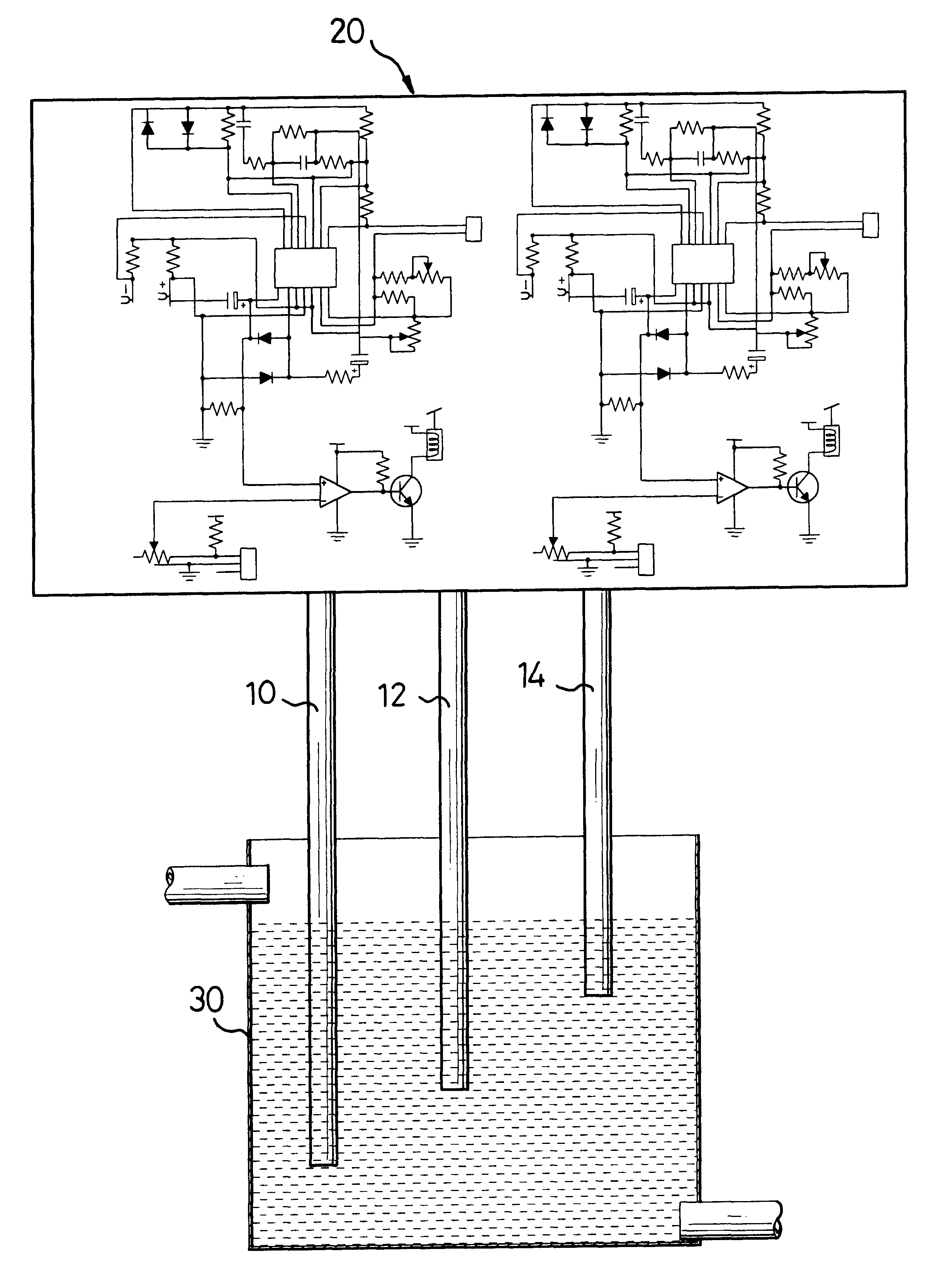
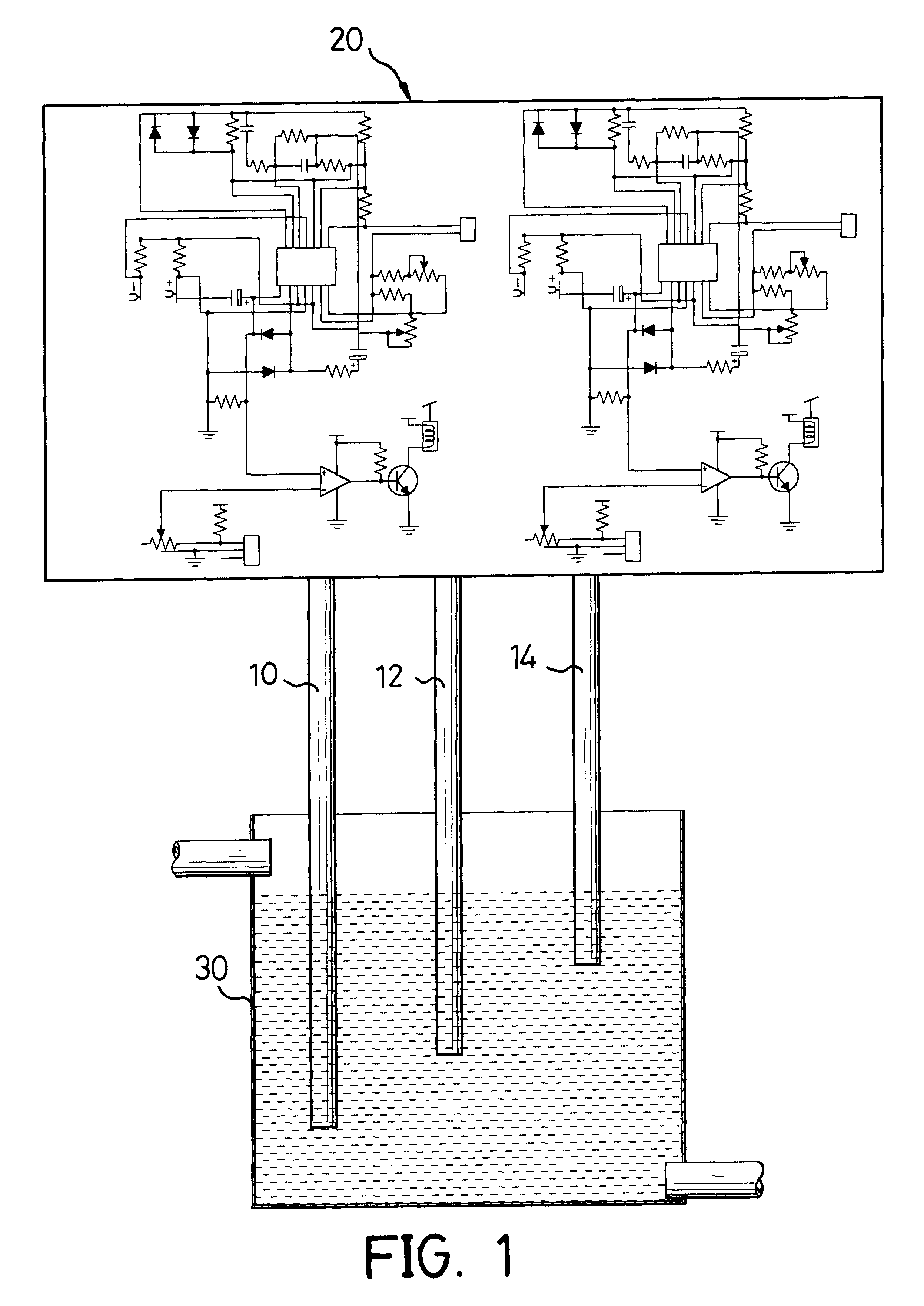
Referring to FIG. 1, a water level controller in accordance with the present invention comprises control circuitry (20) and multiple conductance terminals (10, 12, 14) each connected to the control circuitry (20), where conductance is the inverse of the resistance, as shown in FIG. 4. Each conductance terminal (10, 12, 14) is located at a different height from the others. Preferably, there are three conductance terminals (10, 12, 14) in the controller. A first and second terminal (10, 12) are located near the bottom of the tank (30) with the second terminal (12) not lower than the first terminal (10). A third terminal (14) is located near the top of the tank (30), and higher than the first and the second terminals (10, 12).

With reference to FIGS. 1 and 2, all of the conductance terminals (10, 12, 14) are initially inserted into the water contained in the tank (30). Thus, each terminal (10, 12, 14) can cooperate with the other one to measure the conductance of the water, even pure wa...


PUM


Abstract

A water level controller for a tank has control circuitry and multiple conductance terminals connected to the control circuitry and located at different heights from the other. By such an arrangement, the water level can be determined when the conductance of the water measured by corresponding conductance terminals becomes zero. The water inlet can be controlled to add to the tank by the control circuitry as the conductance measured by two of the corresponding terminals becomes practically negligible. Consequently, the water level in the tank can be accurately controlled, and the controller can be used with pure water so as to enlarge the useful scope of the controller.

Description

1. Field of the InventionThe present invention relates to a water level controller, and more particularly to a water level controller with conductance terminals to control the water level in a tank.2. Description of Related ArtLarge amounts of water are used in many industrial processes. To accommodate the large quantities of water that are periodically required, tanks are used to store the reserve water. To keep the tank from running dry, a water level controller is mounted in the tank to control the water level in the tank. A conventional water level controller is a buoyant, hollow ball attached to one end a lever. The other end of the lever is pivotally connected to an inlet valve in the tank, such that the ball will move up or down according to the height of the water level as the ball floats on the surface of the water. When the water level goes down, the controller will open the inlet valve and allow water to flow into the tank to raise the water level in the tank. When the wa...

Claims


Application Information

Patent Timeline
Patent Type & Authority Patents(United States)
IPC IPC(8): G01F23/24
CPCG01F23/243
Inventor CHEN, PO-HUEI
Owner CHEN PO HUEI
Why Eureka
Try Eureka