
String trimmer head

a trimmer and head technology, applied in the field of head, can solve the problems of cumbersome disassembly of the head and a certain amount of dexterity

Inactive Publication Date: 2002-02-19
BRIGGS & STRATTON POWER PRODS GROUP
View PDF25 Cites 60 Cited by
  • Summary
  • Abstract
  • Description
  • Claims
  • Application Information

AI Technical Summary

Problems solved by technology

Such disassembly of the head is cumbersome and requires a certain amount of dexterity by the operator of the trimmer.

Method used


Image

  • String trimmer head
  • String trimmer head
  • String trimmer head

Examples


Embodiment Construction

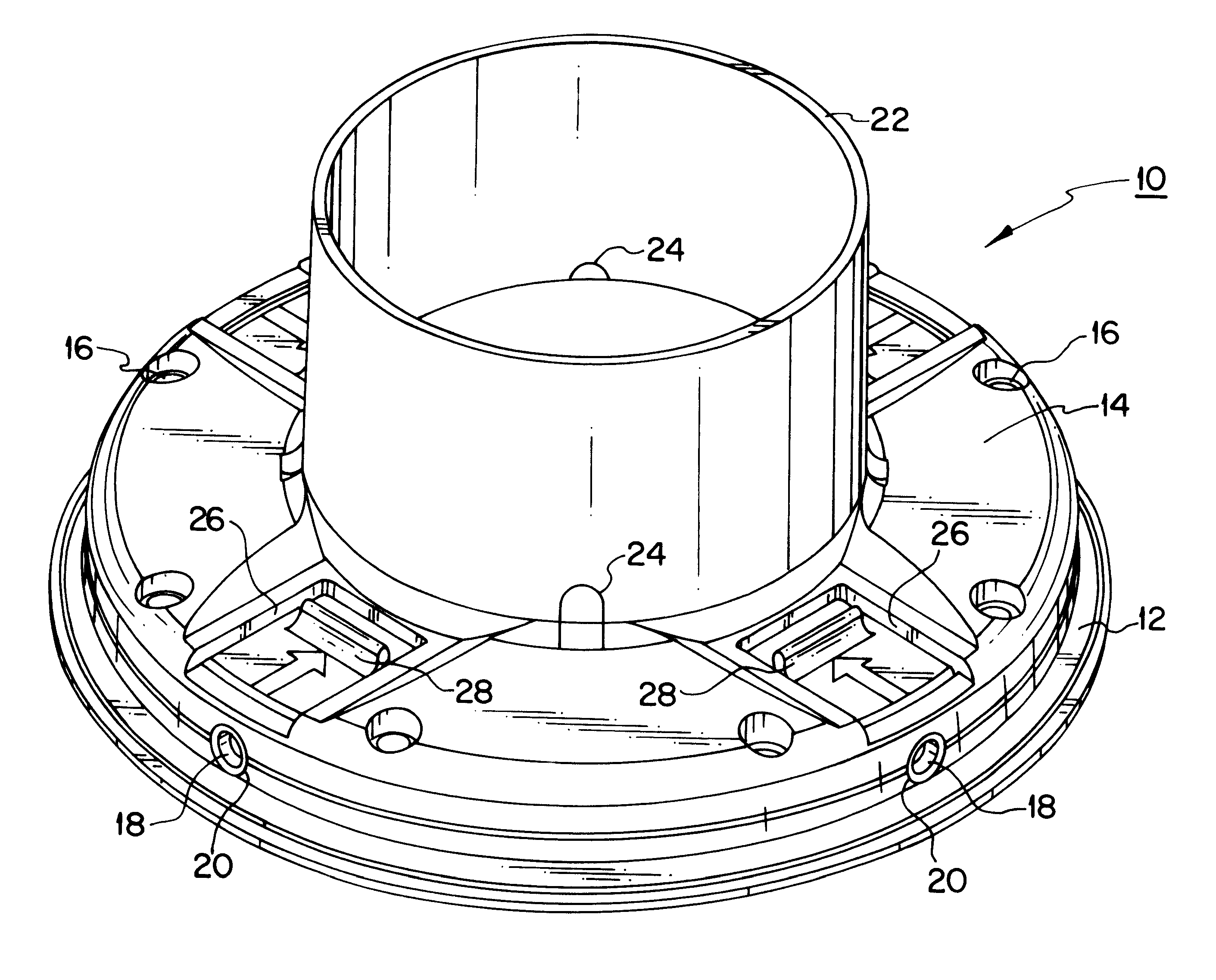
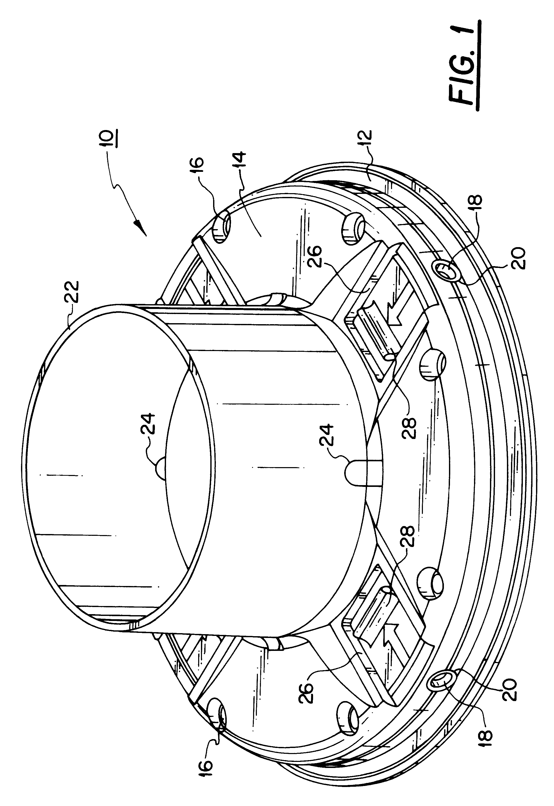
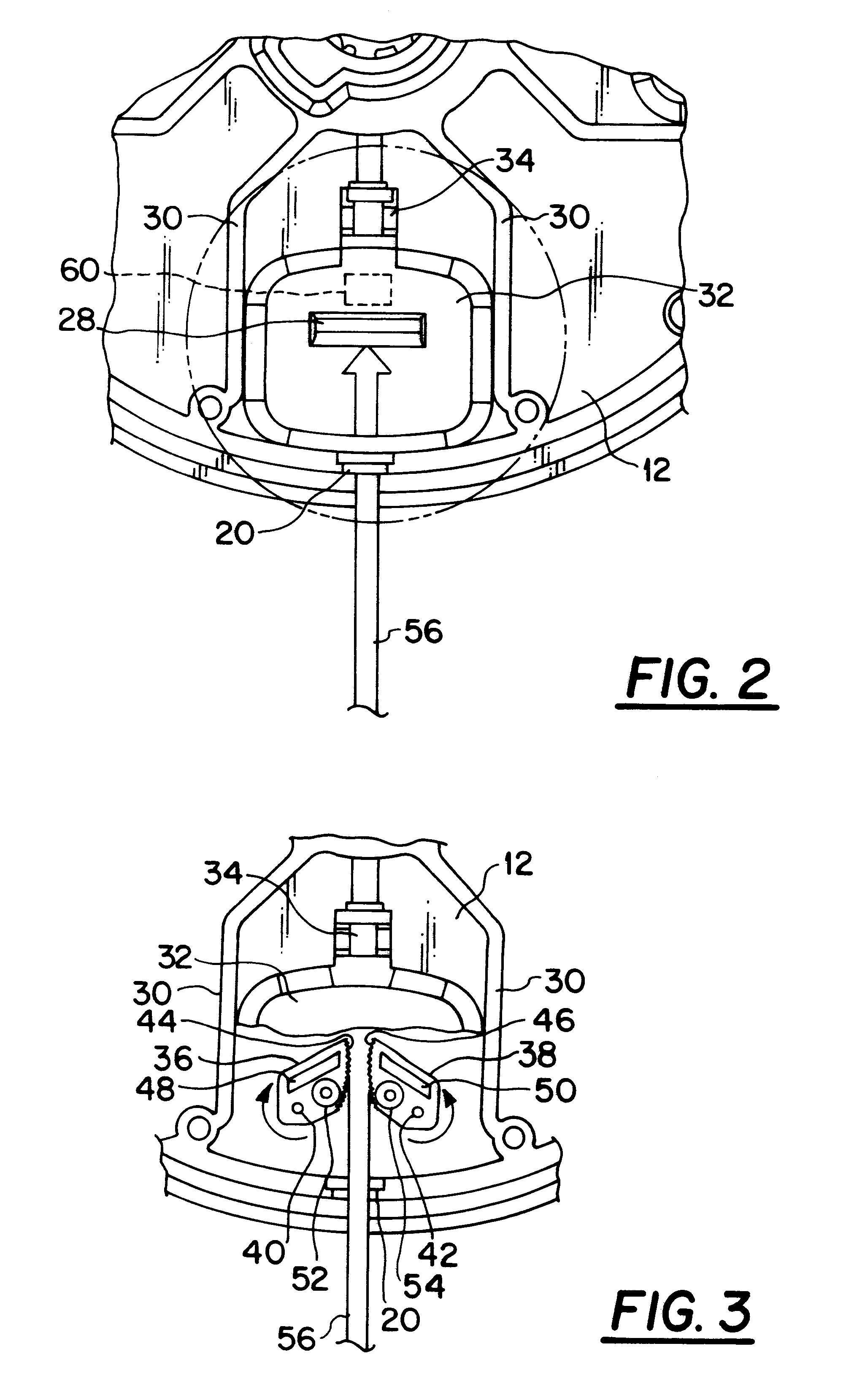
Referring to FIG. 1, a trimmer head 10 comprises a base portion 12 and a cover portion 14. The base and cover portions are held together by fasteners 16, such as screws. The mating sidewalls of the base and cover portions are provided with aligned semi-circular notches so as to define a plurality of openings 18 providing access to the interior of the head. The openings are arranged at spaced locations about the periphery of the head. In the embodiment illustrated, openings 18 are disposed at 90.degree. spacings about the head. Each opening receives an eyelet or grommet 20 which provides a smooth surface for string passing through the openings thereby reducing wear on the strings during operation.

A collar or hub 22 is mounted on the upper surface of the cover portion 14 to surround and shield a drive arrangement (not shown) which extends to the trimmer head from a conventional trimmer motor and handle (also not shown for convenience of illustration). The base of hub 22 is provided wi...


PUM


Abstract

A string trimmer head is provided for receiving and retaining separate lengths of string supplied from outside the head. String lengths passing through openings in the periphery of the head are held by clamping members provided within the head. The clamping members are selectively opened by activation of respective slidable members provided on the upper surface of the head in order to release short lengths of previously supplied string and / or to permit the receipt of new string lengths. On release of the slidable members, the respective clamping members move towards one another for clamping purposes under the influence of springs.

Description

1. Field of the InventionThe present invention relates to an improved head for a string trimmer of the type which does not use a spooled or coiled supply of string.2. Prior ArtString trimmers are well known wherein a spool or coil of string is retained within the head of the trimmer. Such arrangement requires that the head be disassembled when a new supply of string becomes necessary. Additionally, when the string breaks, the head often must be disassembled in order to correct the problem and to adjust the string supply for resumption of operation. Such disassembly of the head is cumbersome and requires a certain amount of dexterity by the operator of the trimmer.To overcome deficiencies of the type just described, attempts have been made to supply string to a trimmer head from outside the head.An example of such an arrangement is disclosed in U.S. Pat. No. 5,758,424 wherein a pair of spring-loaded cams are disposed within the trimmer head at locations adjacent openings in the sidew...

Claims


Application Information

Patent Timeline
Patent Type & Authority Patents(United States)
IPC IPC(8): A01D34/412A01D34/416
CPCA01D34/416
Inventor BRANT, RONALD G.BEAFORE, JOHN L.
Owner BRIGGS & STRATTON POWER PRODS GROUP
Learn More