Hooked latch with ball lock sliding sleeve retainer

a technology of sliding sleeve retainer and latch, which is applied in the direction of mechanical equipment, cables, vehicles/pulleys, etc., can solve the problem of difficulty in removing the hoop from the hook

Inactive Publication Date: 2002-03-26
DYKSTRA PENELOPE RAE +1
View PDF13 Cites 49 Cited by
  • Summary
  • Abstract
  • Description
  • Claims
  • Application Information

AI Technical Summary

Problems solved by technology

Hook latches require various methods of removing the bridge across the hook opening, and in some cases...

Method used


Image

  • Hooked latch with ball lock sliding sleeve retainer
  • Hooked latch with ball lock sliding sleeve retainer
  • Hooked latch with ball lock sliding sleeve retainer

Examples


embodiment

FIG. 7--Additional Embodiment

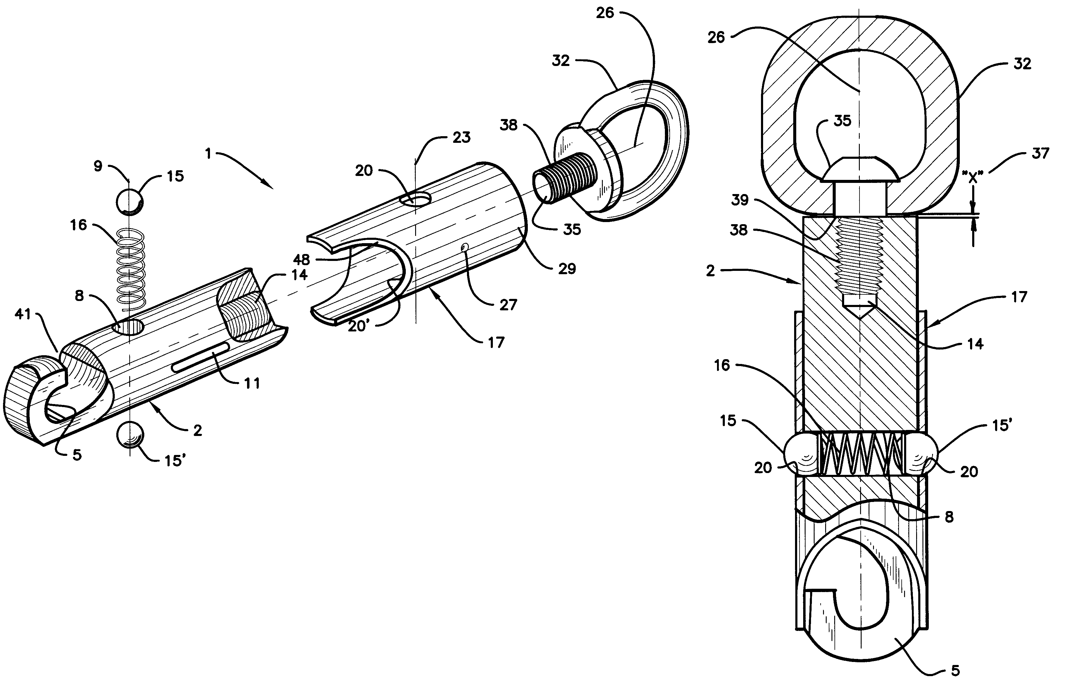
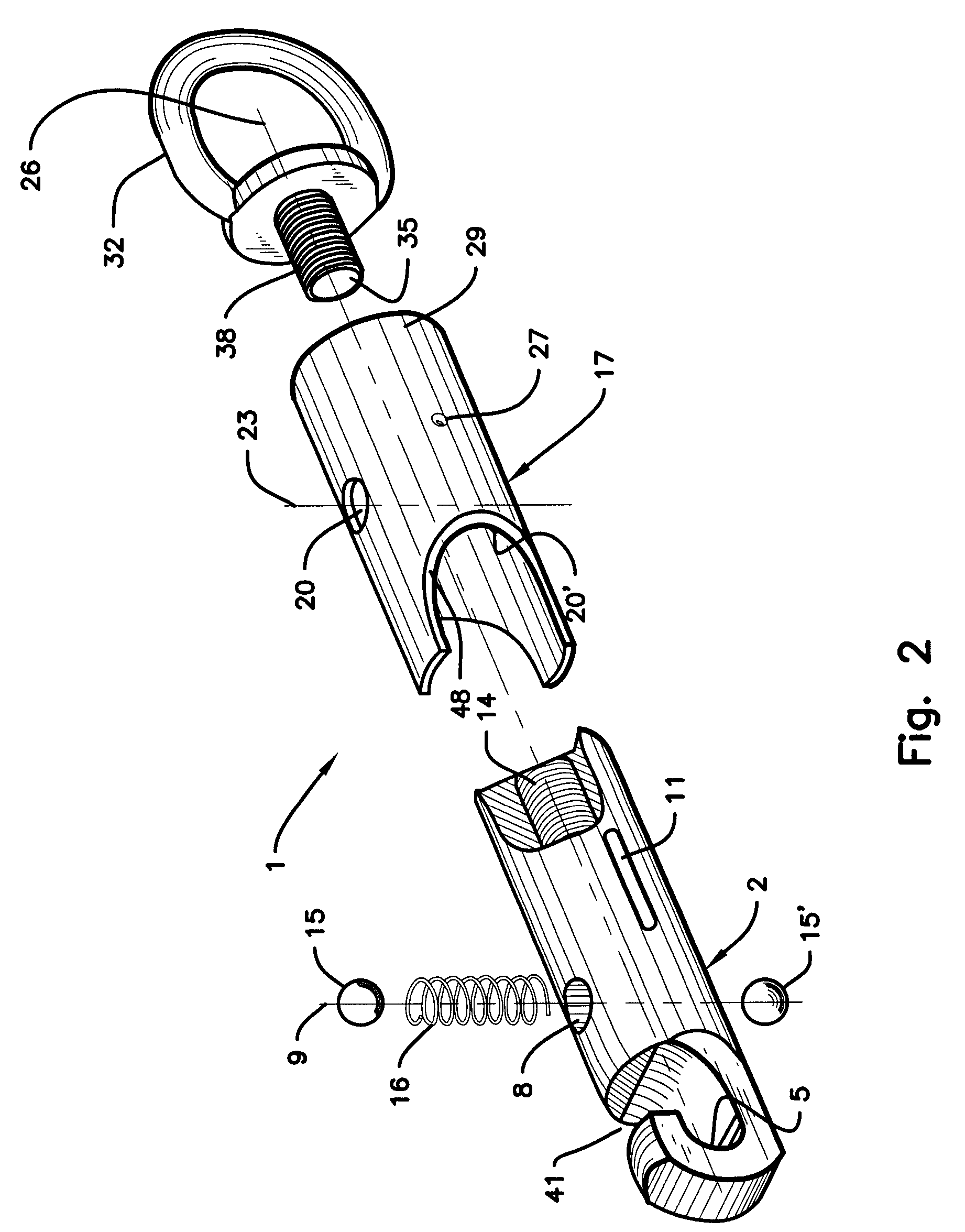
Best seen in FIG. 7, said latch assembly 1 is shown in the open position with said dimple 27 depression shown at the upper slot end surface 12 of slot 11. In this position the sliding sleeve 17 is restrained by the dimple 27 engaging slot end surface 12 from moving up and maintaining alignment of holes 20 and 20' with hole 8 in the hook body 2.

Advantages

From the description above, a number of advantages of our hook latch with ball lock sliding sleeve retainer become evident.

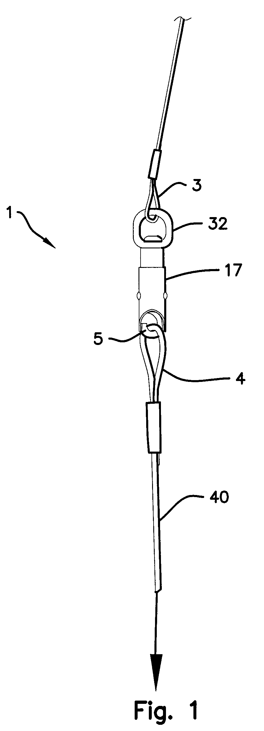
(a) The sliding sleeve 2 does not interfere with the cordage loop 4 when installing or removing the loop 4 from the hook opening 41.

(b) The indicated surfaces of the hook body 2 is scalloped 48 as shown in FIG. 7 to provide a smooth transition surface to avoid sharp comers and edges that will interference with the placing of the cordage loop 4 over the hook 5 when attaching cables.

(c) The body 2 of the latch assembly 1 were deliberately made long to allow for a good grip of the assemb...


PUM


Abstract

An improved hook latch mechanism, for use with cordage loops, used for leashes, cables, ropes, rigging or like restraining devices having a center body hook with a sliding outer sleeve to cover and uncover the hook opening. A spring loaded ball locking device is employed to lock the sliding sleeve in position to cover the hook opening to thus prevent the cordage loops from slipping off the hook, depressing the ball inwardly against a spring and sliding the sleeve upwardly to uncover the hook opening, permitting the removal of the cordage loop. A swiveling bail link at the other end of hook prevents twisting of the cordage loop.

Description

BACKGROUND--FIELD OF INVENTIONThis invention relates to a hook latch mechanism used to attach various cordage loops such as leashes, cables, ropes, rigging or like restraining devices; a protective sleeve covers the hook opening to prevent slippage of the cordage loop off the hook, wherein a spring loaded ball detent lock arrangement is employed to lock the sleeve over the hook opening preventing the cordage loop from slipping off the hook. The sleeve is quickly moved from the hook opening by depressing the ball lock, while simultaneously sliding the sleeve to uncover the hook opening to remove the cordage loop.BACKGROUND--DESCRIPTION OF PRIOR ARTHook latches or like devices come in various sizes and configurations and are used in numerous applications to connect various cordage. Means of retaining the cordage loop onto the hook to prevent slippage, are spring loaded pivot retainers which bridge the hook opening, leaf spring retainers fastened at one end and butted up against the ho...

Claims


Application Information

Patent Timeline
IPC IPC(8): F16G11/10F16B45/00F16G11/00F16B45/04
CPCF16B45/04F16G11/10Y10T24/45293Y10T24/3984Y10T24/3993Y10T24/45304F16B45/051F16B45/045
Inventor DYKSTRA, PENELOPE RAEMOSES, MOLLY JO
Owner DYKSTRA PENELOPE RAE
Why Eureka
Try Eureka