Orthodontic bracket and its tool

a technology of orthodontic brackets and tools, applied in dental tools, dental surgery, medical science, etc., can solve the problems of affecting the comfort of patients, requiring a lot of chair time, and inability to eliminate the force of elastomeric ligature rings

Inactive Publication Date: 2002-04-09
TOMY CHOFU TOKIOTOKYO JP
View PDF5 Cites 127 Cited by
  • Summary
  • Abstract
  • Description
  • Claims
  • Application Information

AI Technical Summary

Problems solved by technology

In addition, the frictional force cannot be eliminated with the elastomeric ligature ring.
This operation requires much chair time and imparts discomfort to the patients.
Such modes of attachment lead to problems of food residues tending to adhere.
In addition, there are cases where the ligature wire causes the trouble of imparting stimuli to the soft tissue of the patient's tongue or cheek as its bent end becomes exposed from below the tie wing.
If this ligature wire is cut and reshifted, the patient may swallow the dislocated ligature wire, or the treatment may make no progress.
In such a state, the arch wire 50 fails to shift smoothly inside the slot, and a hindrance is cau

Method used


Image

  • Orthodontic bracket and its tool
  • Orthodontic bracket and its tool
  • Orthodontic bracket and its tool

Examples


first embodiment

(First Embodiment)

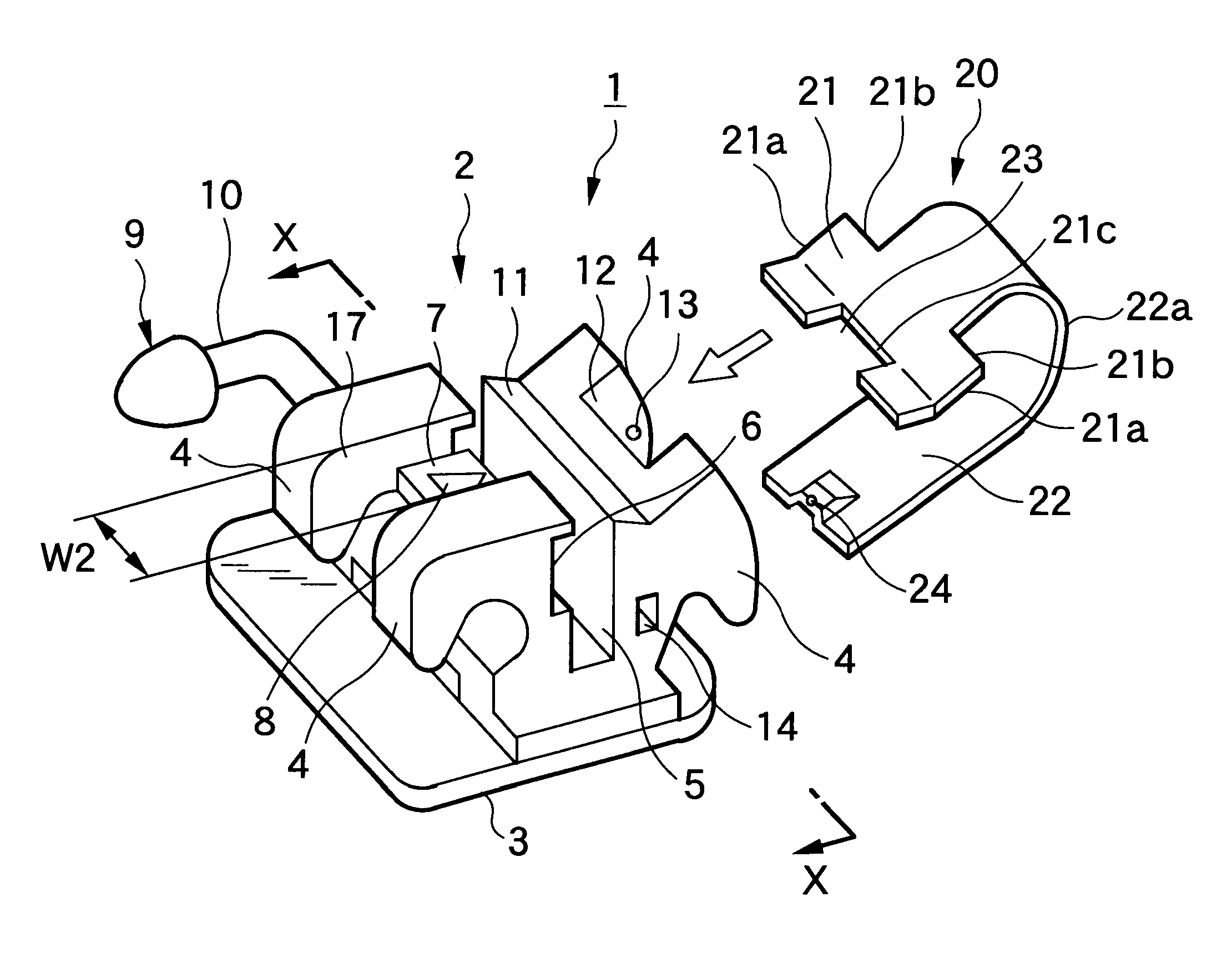
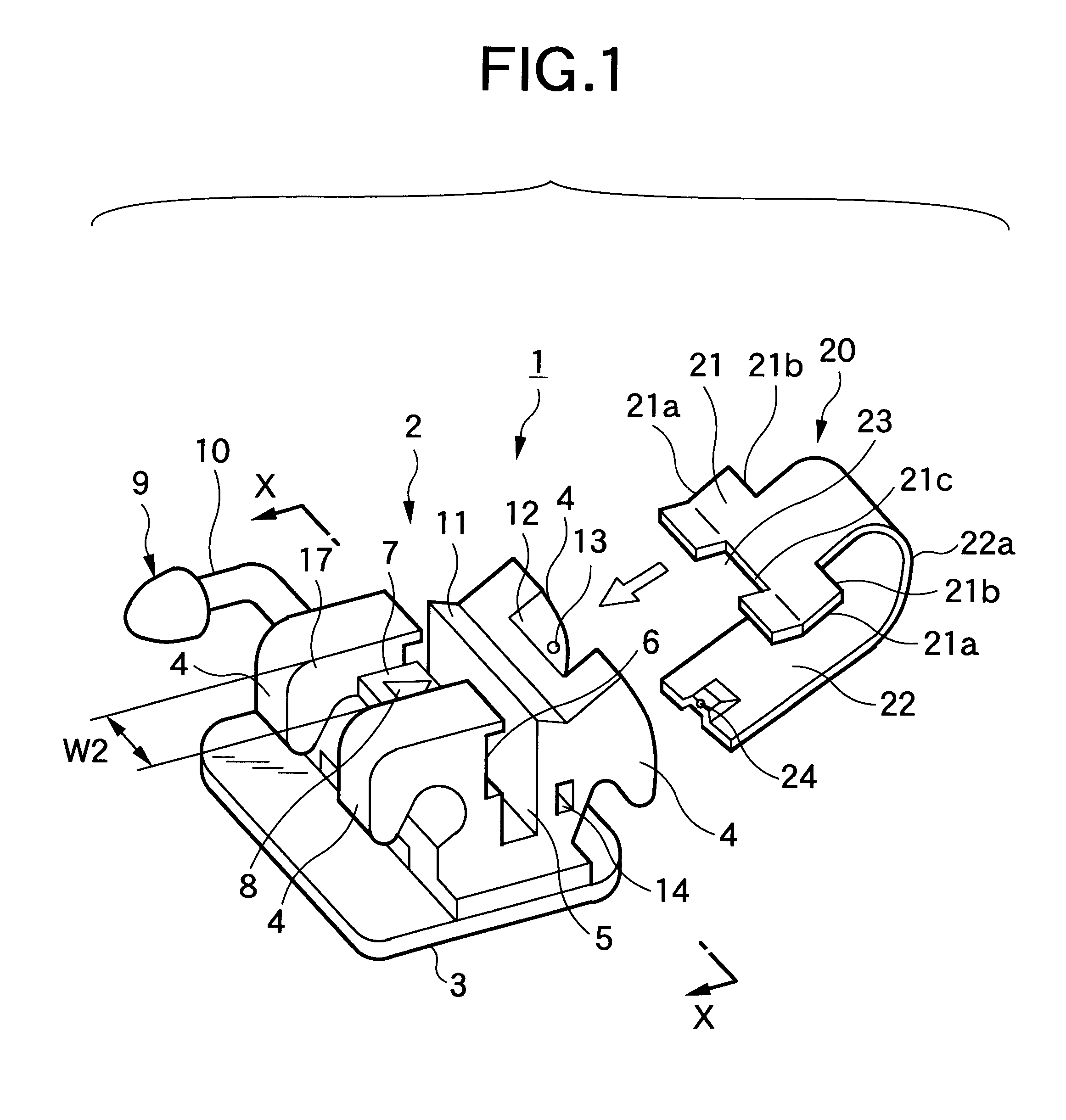
An orthodontic bracket 1 in accordance with the first embodiment shown in FIGS. 1 and 2 is a twin bracket having a central groove 17 enclosed by mesial tie wings 4 and distal tie wings 4. This bracket 1 is provided with a base 3 secured to a tooth surface, a bracket body 2 extending in a substantially perpendicular direction from the base, and an arch wire slot 5 which extends in a mesiodistal direction substantially in the center of the bracket body 2 and is open in the front. The bracket 1 is provided with a locking member 20 capable of opening or closing the arch wire slot 5.

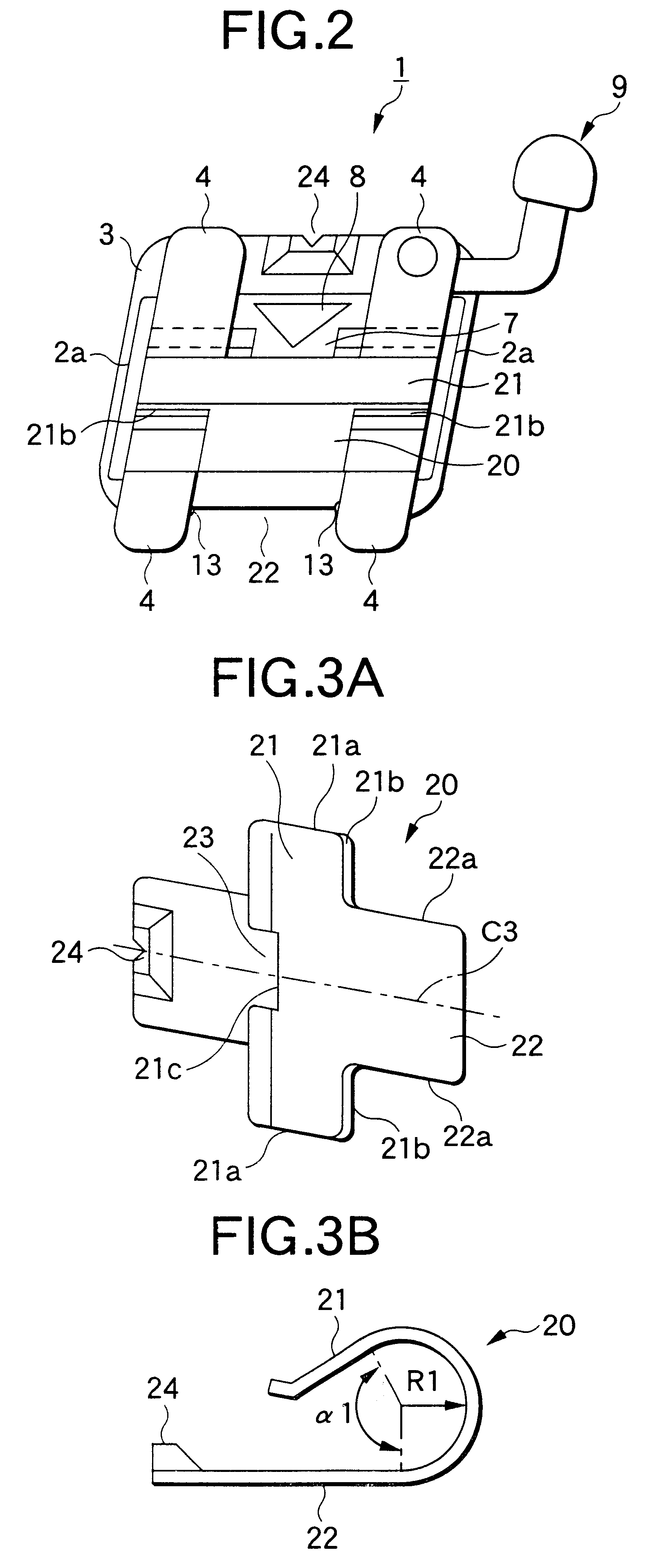
As shown in FIGS. 1 and 3, this locking member 20 is structured in a substantially U-shaped cross-sectional configuration, and one side thereof is formed as a base side portion 22 (a portion located on the lingual side) located on the base side and extending along the base, while the other side thereof is formed as a counter base side portion 21 having substantially the same width as the len...

second embodiment

(Second Embodiment)

A description will be given of a tool for an orthodontic bracket which is used for the orthodontic bracket 1 shown in the above-described first embodiment.

The tool 70 for an orthodontic bracket in this embodiment is not particularly limited to the illustrated form insofar as a first arm portion 71 and a second arm portion 72 are arranged to be appropriately continuous as shown in FIG. 8, and it is possible to adopt various forms.

In short, the tool 70 for an orthodontic bracket includes the first arm portion 71 which is a fulcrum portion for engagement with the bracket body 2 (in this embodiment, the recessed portion 8 in the upper end surface of the rib 7 provided on the bracket body 2), and the second arm portion 72 which serves as an acting portion for engagement with the engaging end portion 24 (e.g., a notched portion, a recessed portion, a projection, or the like) formed at the rear end portion of the base side portion 22 in the locking member 20.

Since the to...

third embodiment

(Third Embodiment)

Referring now to FIG. 9, a description will be given of a third embodiment of the invention.

An orthodontic bracket 91 in accordance with the third embodiment shown in FIG. 9 is a single bracket in which a bracket body 92 has a pair of tie wings 94, and this bracket 91 is consisting of a base 93 secured to a tooth surface, a bracket body 92 extending in a substantially perpendicular direction from the base 93, and an arch wire slot 95 which extends in the mesiodistal direction substantially in the center of the bracket body 92 and is open in the front. The bracket 91 is provided with a locking member 920 capable of opening or closing the arch wire slot 95.

This locking member 920 has on one side thereof a base side portion 922 located on the base side and extending along the base, and on the other side thereof a counter base side portion 921 having substantially the same width as the length of the arch wire slot 95 and extending on the upper side of the slot. The loc...


PUM


Abstract

An orthodontic bracket has a locking member, one side of which is formed as a base side portion located on a base side and extending along the base, and the other side of which is formed as a counter base side portion having substantially the same width as the length of an arch wire slot 5 and extending on an upper side of the slot. The locking member is formed of an elastic member in which a notched portion is provided substantially in a center of the base side portion. Further, a bracket body has a closing stop groove formed at an open edge portion of the arch wire slot so as to stop a tip of the locking member in a slot closed position as well as an open stop concavity formed at an edge portion thereof located away from the stop groove so as to stop the tip of the locking member in a slot open position. A rib is formed in a longitudinally central portion of the stop groove in such a manner as to project so as to bury the stop groove in correspondence with the notched portion.

Description

1. Field of the InventionThe present invention relates to an orthodontic bracket, and more particularly to an orthodontic bracket having a shiftable locking member so as to open or close an arch wire slot in a bracket body as well as a tool for an orthodontic bracket.2. Description of the Related ArtAs is known, orthodontic treatment is effected by fixing small appliances called orthodontic brackets to a patient's teeth. Namely, the orthodontic brackets are most commonly used by being fixed to the patient's teeth in an appropriate manner so as to correct the misaligned teeth by applying an external force thereto through an arch wire extending between the fixed orthodontic brackets.As to the structure of these orthodontic brackets, they are constructed of a body having small slots and are adhered directly on the labial or lingual sides of the teeth or welded to such as metal bands attached to the teeth by cementing or by some other method.As the form of use of the orthodontic bracket...

Claims


Application Information

Patent Timeline
IPC IPC(8): A61C7/00A61C7/28A61C7/30A61C7/14
CPCA61C7/282A61C7/30A61C7/287
Inventor VOUDOURIS, JOHN C.ORIKASA, MASAAKI
Owner TOMY CHOFU TOKIOTOKYO JP
Why Eureka
Try Eureka