Highly compliant retention mechanism for attaching and quickly releasing components

Inactive Publication Date: 2002-04-23
VERMILLION DEFENSE
View PDF13 Cites 16 Cited by
  • Summary
  • Abstract
  • Description
  • Claims
  • Application Information

AI Technical Summary

Problems solved by technology

This common design requires three or more parts that are required to interlock, thereby increasing the number of steps and the time required to assemble and disassemble the components.
Although a reservoir in th

Method used


Image

  • Highly compliant retention mechanism for attaching and quickly releasing components
  • Highly compliant retention mechanism for attaching and quickly releasing components
  • Highly compliant retention mechanism for attaching and quickly releasing components

Examples


Example

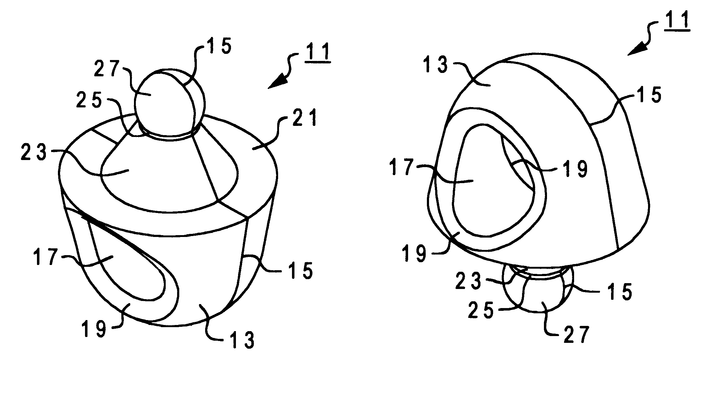
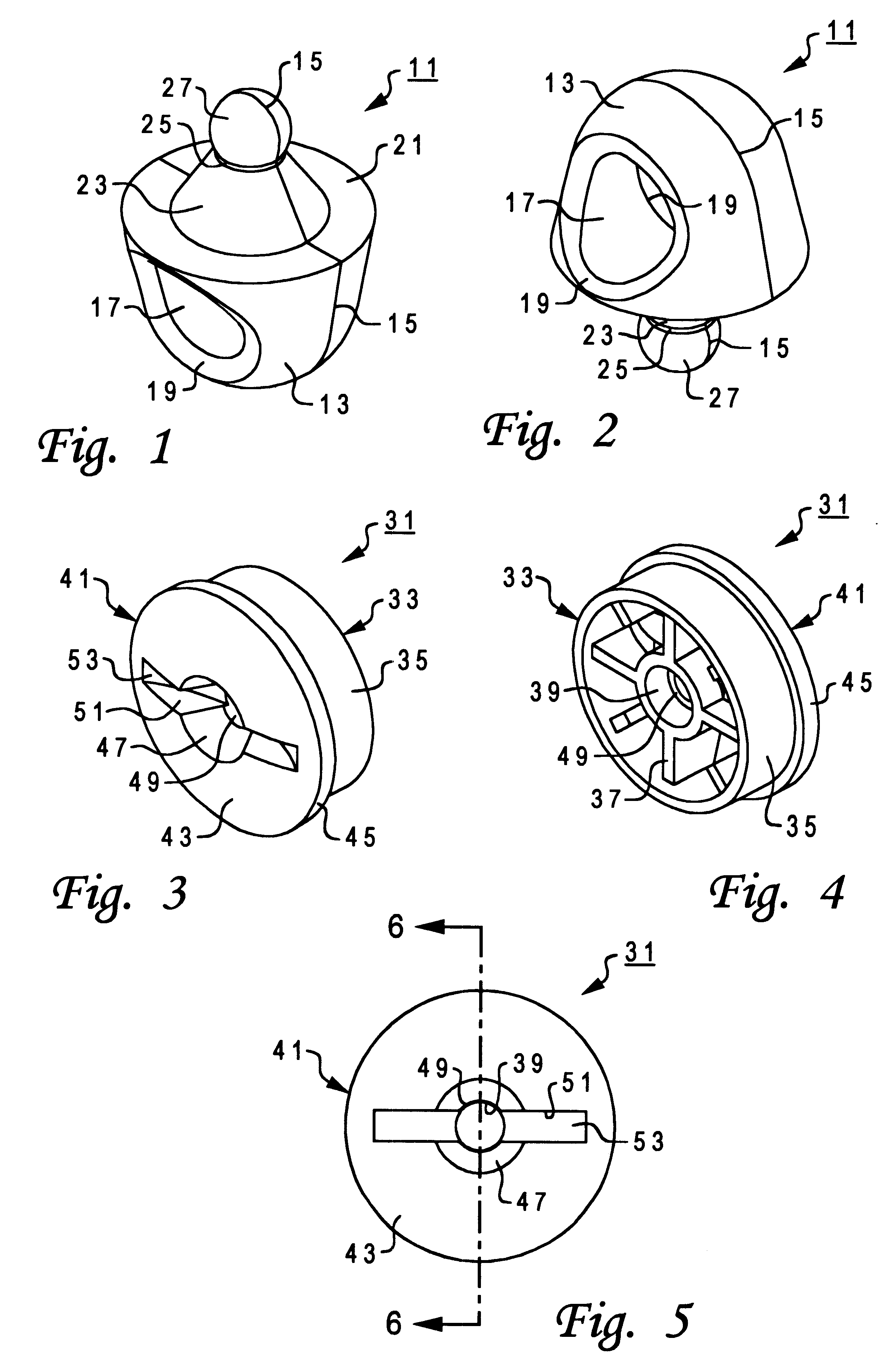
Referring to FIGS. 1 and 2, a snap ring 11 constructed in accordance with the invention is shown. Snap ring 11 has a generally semi-spherical lower body 13 that is bisected by a small ridge 15. Ridge 15 is provided for manufacturing purposes and extends completely around the exterior of snap ring 11. Snap ring 11 is symmetrical about ridge 15 and about a plane (not shown) that perpendicularly bisects ridge 15 and snap ring 11. Lower body 13 has a large body attachment feature comprising, in the embodiment shown, an opening or hole 17 that extends completely through lower body 13 from one side to an opposite side. Lower body 13 also has an annular concave taper 19 on each of its sides that is provided between the exterior of lower body 13 and hole 17. Tapers 19 are beveled to facilitate entry into hole 17 by an object being attached to snap ring 11 (e.g., a key ring, etc.).

In this embodiment, lower body 13 terminates with a flat upper surface 21 having a circular perimeter. A general...


PUM


Abstract

A two-piece retention mechanism has a base and a snap ring that are individually mounted to two separate components that a user desires to releasably join. The snap ring has a round body with a hole for attaching the first component thereto. A conical element with a spherical tip protrudes from the snap ring body. The base has a cylindrical body for mounting to the second component. The body of the base has a cap with a rounded face and a conical opening that tapers down to a cylindrical hole. After the base and snap ring are mounted to their respective components, the snap ring may be removably connected to the base by inserting its spherical tip into the conical opening in the base. The complementary shapes of the snap ring and base allow for significant axial and angular misalignment. The snap ring and base elastically deform and emit an audible "snap" during this sequence. To disengage the snap ring from the base, the user simply pulls the snap ring away from base to overcome the retention forces.

Description

1. Technical FieldThe present invention relates in general to an improved retention mechanism, and in particular to an improved mechanism for releasably joining components. Still more particularly, the present invention relates to a highly compliant retention mechanism for attaching and quickly releasing components.2. Description of the Related ArtRetention devices or mechanism for releasably joining two or more components are common and quite varied in the prior art. For example, one type of swivel snap hook device typically comprises a hook member attached to a first object, and an eye member attached to a second object. The hook member is then rotatably connected to the eye member with a separate retaining member. This common design requires three or more parts that are required to interlock, thereby increasing the number of steps and the time required to assemble and disassemble the components. U.S. Pat. No. 4,599,767 simplifies this common design to only two components, but the...

Claims


Application Information

Patent Timeline
IPC IPC(8): F16B45/00
CPCF16B45/00Y10S24/905Y10T24/45152Y10T24/4522Y10T24/4755Y10T24/3424Y10T24/45775F16B45/002F16B17/00
Inventor CARDWELL, III, WALTER WILCOXSTICKEL, STEPHEN ANDREWTRAN, AN
Owner VERMILLION DEFENSE
Why Eureka
Try Eureka