Developing unit equipped with a toner replenishing device configured with a conveying sheet and rotator

a development unit and toner replenishment technology, applied in the direction of instruments, electrographic process equipment, optics, etc., can solve the problems of insufficient agitation and conveyance of toner in the left and right or lateral direction, and the toner inside the toner reserve container 64 cannot be completely used

Inactive Publication Date: 2002-05-07
SHARP KK
View PDF12 Cites 38 Cited by
  • Summary
  • Abstract
  • Description
  • Claims
  • Application Information

AI Technical Summary

Problems solved by technology

In a developing unit of the above type, if the toner reserve container for replenishing the developing hopper with the developer is arranged on the top, the developing unit would be bulky as to its height so a waste space would arise inside the image forming apparatus, thus making the whole image forming apparatus bulky.
That is, if the distance of conveying sheet 68 from the fixed end to the distal end is set long enough to convey the toner in the vertical direction, it is difficult to secure good enough performances of agitation and conveyance of the toner in the left and right, or lateral direction.
As a result, the toner inside toner reserve contai...

Method used


Image

  • Developing unit equipped with a toner replenishing device configured with a conveying sheet and rotator
  • Developing unit equipped with a toner replenishing device configured with a conveying sheet and rotator
  • Developing unit equipped with a toner replenishing device configured with a conveying sheet and rotator

Examples


first embodiment

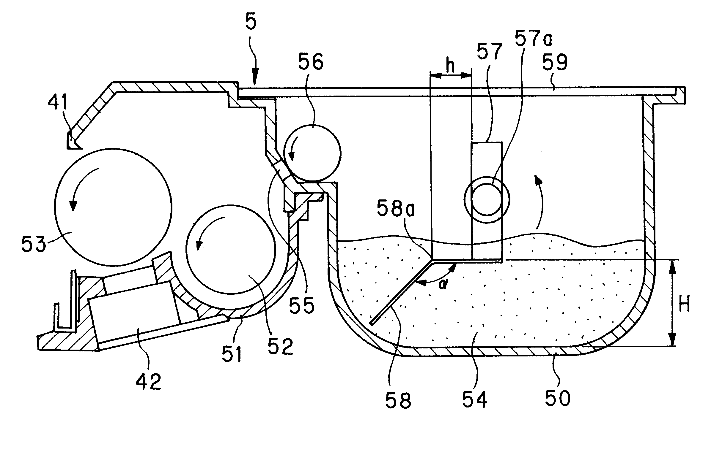
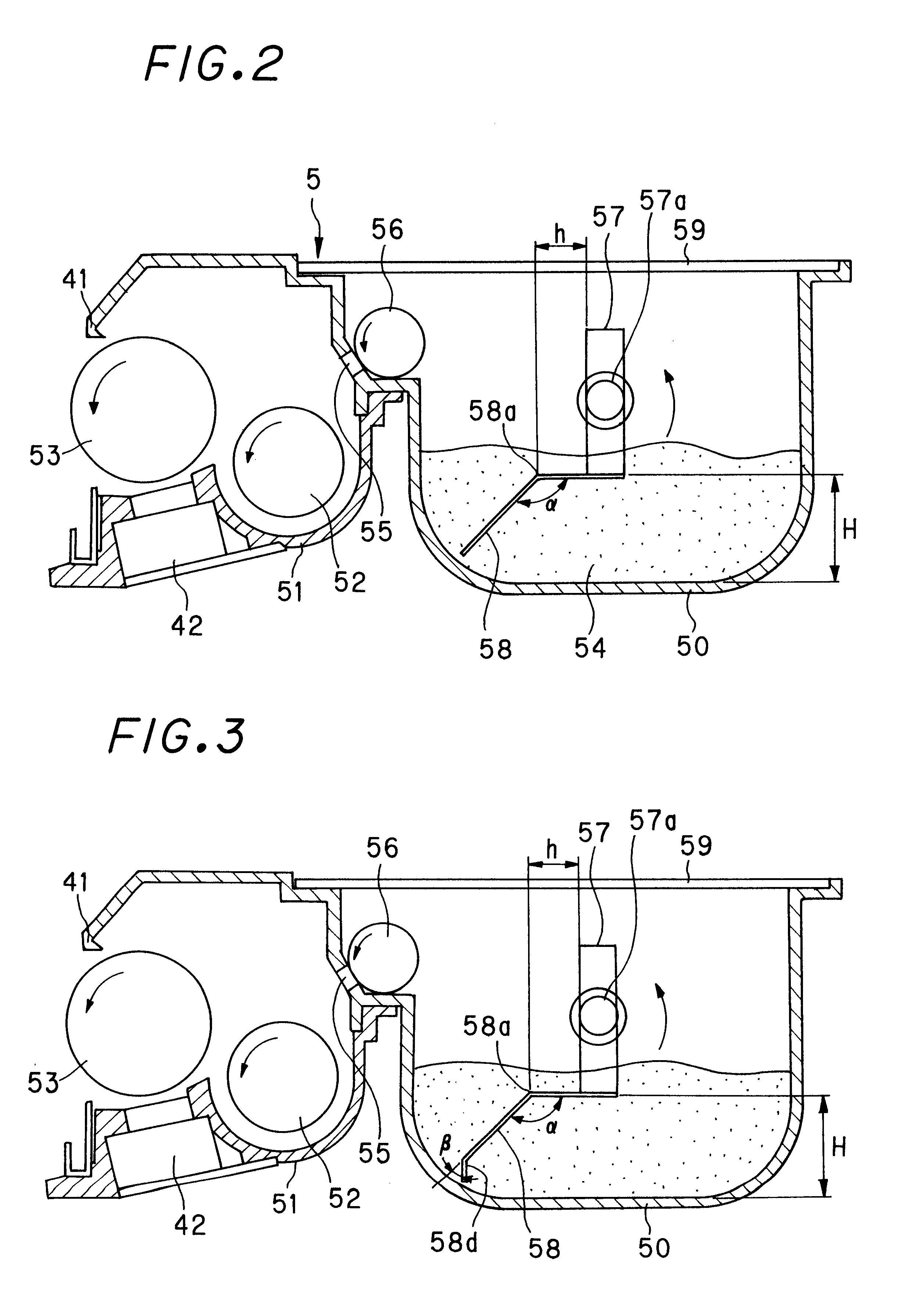
FIG. 2 shows the configuration of developing unit 5 in accordance with the invention as stated heretofore. In FIG. 2, developing unit 5 has a toner replenishing device having a toner reserve container 50 storing the toner. This toner reserve container 50 is horizontally arranged at the side of a developing hopper 51 as a part of developing unit 5.

As conventionally known, developing hopper 51 storing the developer in developing unit 5 is provided with a rotatable, agitating roller 52 for agitating and conveying the developer stored therein and a rotatable, developing roller 53 for conveying the developer to the developing area facing the image forming portion shown in FIG. 4, in particular, photosensitive member 1, so as to perform development. The aforementioned toner reserve container 50 is arranged adjacent to developing hopper 51.

Though not illustrated, when the developer is comprised of a toner and a carrier, the developing roller 53 is configured of a nonmagnetic, cylindrical s...

second embodiment

The second embodiment is another configuration for eliminating the same problem without bending conveying sheet 58 at a halfway point. The configuration of the conveying sheet 58 of this embodiment will be detailed hereinbelow.

FIG. 12 shows an example of the second embodiment of the present invention. This embodiment is completely the same as that shown in FIG. 2 and 3 and FIG. 11 except in the structure of conveying sheet 58. Therefore, only the structure of conveying sheet 58 will be explained in the following description.

In FIG. 12, conveying sheet 58 is configured of a thicker proximal part which is attached to agitator 57 and a thinner free end part for agitating and conveying toner 54 in toner reserve container 50. More specifically, conveying sheet 58 is composed of a fixed part 58b to be attached and fixed and a conveying part 58c on the free end side and the thickness t1 of fixed part 58b is made greater than the thickness t2 of conveying part 58c (t1>t2).

With conveying she...

third embodiment

The third embodiment is the invention which provide further improved toner conveyance and enables further long termed use of the conveying sheet compared to that achieved by fixed portion 58b of the second embodiment. The detail will be made hereinbelow.

FIG. 13A to 13D show various examples of reinforcing elements 45 provided for securing sufficient rigidity of conveying sheet 58 to reinforce conveying sheet 58. FIG. 13A shows an example of a reinforcing element 45, corresponding to fixed portion 58b of conveying sheet 58, integrally molded with agitator 57 as explained before. This reinforcing element 45 is used to bond conveying sheet 58 thereto.

With this configuration, conveying sheet 58 is reinforced with reinforcing element 45 to have necessary rigidity, thus achieving improved toner conveyance. Further, this configuration of conveying sheet 58 also prevent a large plastic deformation around the attachment edge `d` of agitator 57 shown in FIG. 5, and hence inhibits whitening at...


PUM


Abstract

A developing unit includes a developing hopper, a toner reserve container that incorporates a replenishing roller and a replenishing port forming a toner replenishing portion, arranged adjacent to the developing hopper in order to supply the toner to the developing hopper. The toner reserve container further includes an agitator rotatable about a rotary shaft and a conveying sheet attached to the agitator for conveying the toner to the replenishing roller. The conveying sheet has a bent portion where the conveying sheet is bent in the rotational direction of the agitator at a halfway point thereof with a predetermined angle alpha. Deformation of the conveying sheet during rotation is absorbed around the position of the bent portion, so that the conveying sheet will not be plastically deformed at the attached part of the conveying sheet joined to the attachment edge of the agitator, whereby long stable toner conveyance by the conveying sheet can be maintained.

Description

(1) Field of the InventionThe present invention relates to a developing unit for use in an image forming apparatus such as a laser printer, copier, facsimile machine etc., and in particular relates to a technology for replenishing, as required, the developing hopper as a part of a developing unit, with the toner for image development.(2) Description of the Prior ArtAn image forming apparatus such as a laser printer, copier, facsimile machine, etc., utilizing the electrophotographic technique, has an image forming portion for forming a desired image on a sheet for recording. In this image forming portion, the surface of a photosensitive member as an image bearer is uniformly electrified with charge of a particular polarity and then is illuminated with an optical image so as to form a static latent image corresponding to the image. For the purpose of visualizing this static latent image, the image forming portion includes a developing unit and other components. The developing unit is ...

Claims


Application Information

Patent Timeline
IPC IPC(8): G03G15/08
CPCG03G15/0877G03G15/0875
Inventor ISHIGURO, YASUYUKINAGATA, TSUTOMUKANESHIGE, MASATOSHINISHINO, TOSHIOTANISAWA, HIROSHIYAMAGUCHI, JUNOTSUKA, YOSHINORIARAKI, HIROSHIGE
Owner SHARP KK
Why Eureka
Try Eureka