Straw with plug

a technology of straws and plugs, which is applied in the field of straws with plugs, can solve the problems of user's hands being smeared, insanitation conditions and surrounding contamination, and troublesome to rinse and store used straws separately from beverage containers

Inactive Publication Date: 2002-08-06
KYOWA ELECTRIC & CHEM
View PDF10 Cites 60 Cited by
  • Summary
  • Abstract
  • Description
  • Claims
  • Application Information

AI Technical Summary

Benefits of technology

In view of the foregoing disadvantages inherent in conventional beverage containers, it is an object of the present invention to provide a straw capable of being contained and stored within a capped...

Problems solved by technology

This is done because the beverage container cannot be capped due to the interference with the straw, and even if the beverage container could successfully be capped, the straw could fall down in the container and could be sunk in the remaining beverage so that it would become unable for the straw to be taken out of the beverage container or the straw could be wetted by the beverage throughout its length so that user's hands wo...

Method used


Image

  • Straw with plug
  • Straw with plug
  • Straw with plug

Examples


first embodiment

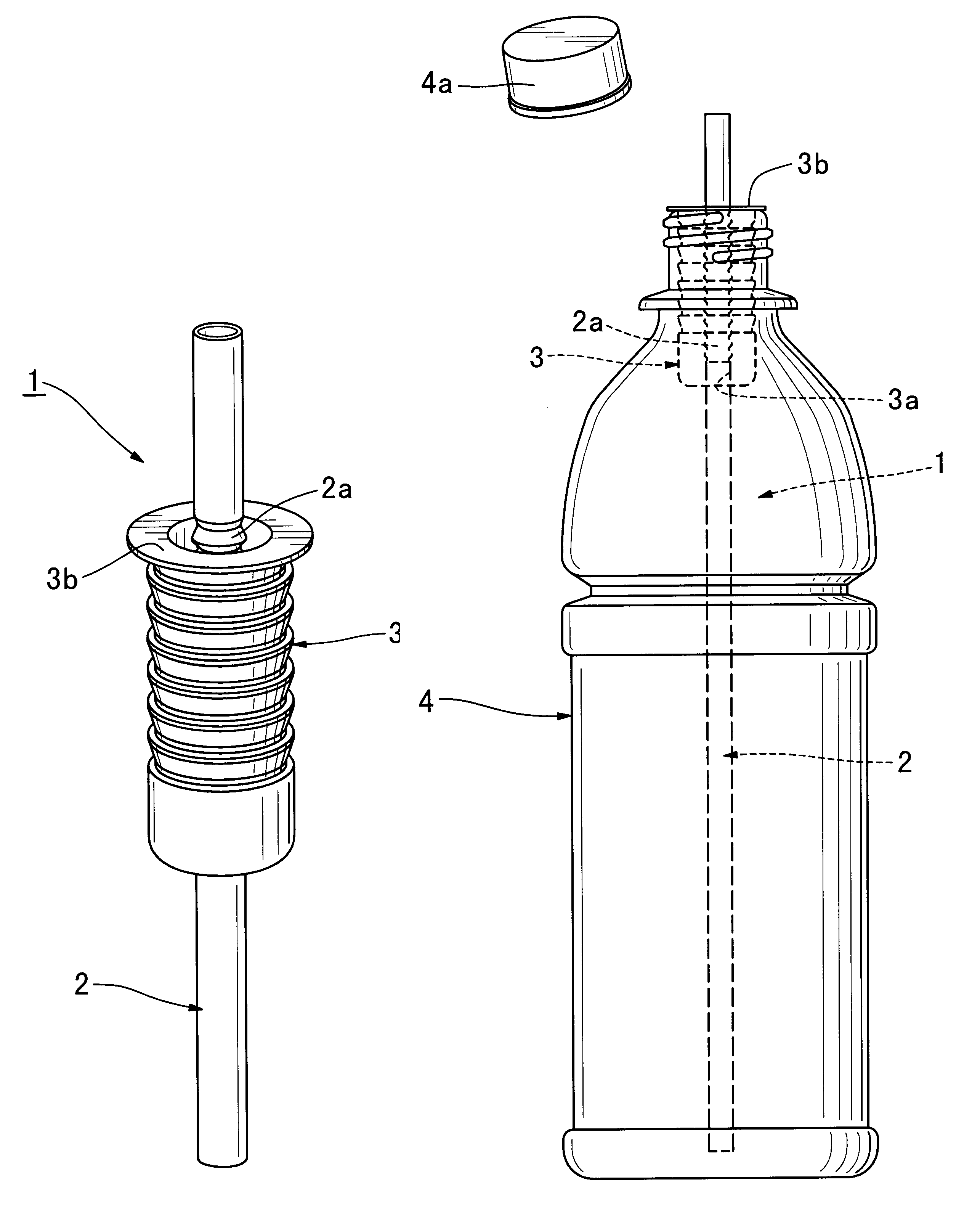
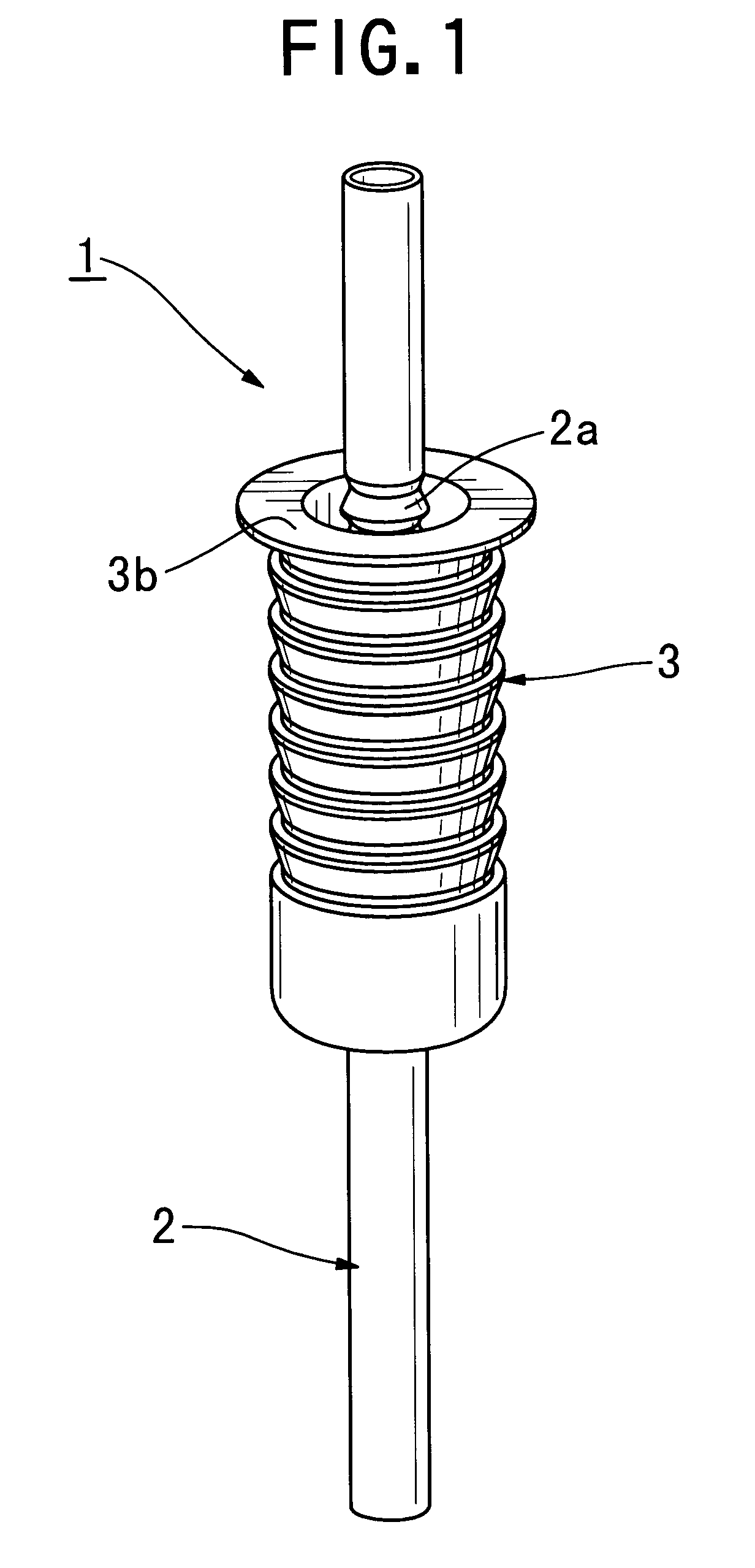
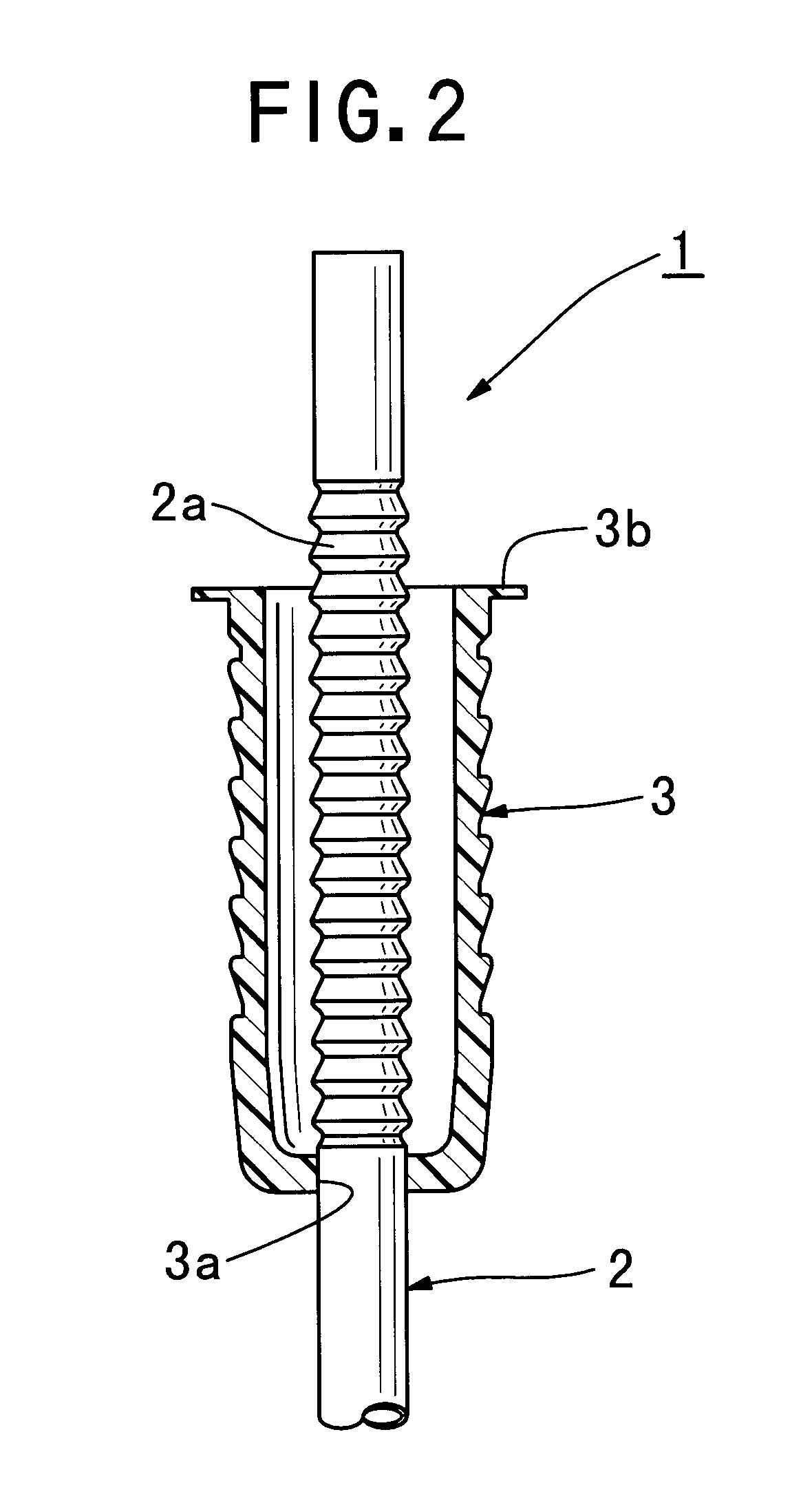
A first embodiment of a straw according to the present invention will be firstly described. FIG. 1 is a perspective view showing the straw according to the present invention, and FIG. 2 is an enlarged cross-sectional view showing an upper section of the straw shown in FIG. 1.

As sown in FIGS. 1 and 2, the straw 1 of the present embodiment is formed of polypropylene and comprises a straw member 2 having an accordion, or bellows type flexible portion 2a, which is retractable or extensible in the longitudinal direction of the straw member, at an upper section of the straw member 2, and a cylindrical plug member 3 having an opening at a top.

A top rim 3b is formed on the top of the plug member 3. The top rim 3b surrounds a periphery of the top of the plug member 3 and protrudes outward therefrom. An aperture 3a is also provided at the center of a bottom portion of the plug member 3, and the straw member 2 vertically extends through the aperture 3a. The accordion flexible portion 2a is loc...

second embodiment

A second embodiment of a straw according to the present invention will be described. FIG. 7 is a perspective view showing the straw according to the present invention, and FIG. 8 is a cross-sectional view showing the straw shown in FIG. 7.

As shown in FIGS. 7 and 8, the straw 5 of the present embodiment is formed of polypropylene, and comprises a straw member 6 and a cylindrical plug member 7 which has an opening at the top thereof. The straw member 6 includes an outer straw portion 6a and an inner straw portion 6b which has a bendable bending portion 6c at an upper section thereof.

A top rim 7b is formed on the top of the plug member 7. The top rim 7b surrounds a periphery of the top of the plug member 7 and protrudes outward therefrom. An air vent 7b is provided in a lower section of a sidewall of the plug member 7. At the center of a bottom portion of the plug member 7, there is provided an aperture 7a and an inserting mouth 7c which surrounds a periphery of the aperture 7a and pro...

third embodiment

A third embodiment of a straw according to the present invention will be described. FIG. 11 is a perspective view showing the straw according to the present invention, and FIG. 12 is a cross-sectional view showing the straw shown in FIG. 11.

As shown in FIGS. 10 and 11, a straw 9 of the present embodiment is formed of polypropylene, and comprises a plug member 10 and a straw member 11.

The plug member 10 includes a plug portion 10a and a cap portion 10b. The plug portion 10a is formed in a cylindrical shape which includes an opening at a top thereof. A top rim 10b is formed on the top of the plug portion 10a. A top rim 10b surrounds a periphery of the top of the plug portion and protrudes outward therefrom. An outer wall 10d is formed on a lower end of the top rim 10c. The outer wall 10d surrounds a sidewall of the plug portion 10a and protrudes downward from the lower end of the top rim 10c. The outer wall 10d is also spaced apart from the sidewall of the plug portion 10a and positio...


PUM


Abstract

A straw comprises a cylindrical plug member having an opening at a top thereof, and a straw member which vertically extends through a bottom portion of the plug member and which is retractable in the longitudinal direction of the straw member, wherein the straw is adapted to fit the plug member with a top of a mouth of a beverage container so as to retain in a state where the straw is inserted into the beverage container. The straw is also adapted to allow a top of the straw member to be protruded from the mouth of the beverage container by extending the straw member and to allow the top of the straw member to be contained within the plug member by retracting the straw member so as to attach a cap of the beverage container.

Description

The present invention relates to a straw, more particularly to a straw capable of being contained and stored within a capped beverage container.In a beverage container or dispenser capable being capped, when the beverage container is to be capped without finishing whole quantity of beverage and leaving a certain amount of beverage therein, a straw which has been in use thus far is usually taken out of the beverage container. This is done because the beverage container cannot be capped due to the interference with the straw, and even if the beverage container could successfully be capped, the straw could fall down in the container and could be sunk in the remaining beverage so that it would become unable for the straw to be taken out of the beverage container or the straw could be wetted by the beverage throughout its length so that user's hands would be made smeary when the straw would be taken out therefrom. The straw which has been taken out of the beverage container will generall...

Claims


Application Information

Patent Timeline
IPC IPC(8): B65D77/28B65D77/24B65D51/24
CPCB65D77/283
Inventor HIROTA, KASHICHIKANEDA, MAKOTO
Owner KYOWA ELECTRIC & CHEM
Why Eureka
Try Eureka