Metal jacket for a cementless artificial joint stem and artificial joint having the jacket

a technology of cementless artificial joints and jackets, which is applied in the field of metal jackets for cementless artificial joints, can solve the problems of accelerating the osteolysis of the bone, weak connection, and risk of impeding the process of ingrowth of bone to the joint stem,

Inactive Publication Date: 2002-12-24
KOREA ADVANCED INST OF SCI & TECH
View PDF9 Cites 42 Cited by
  • Summary
  • Abstract
  • Description
  • Claims
  • Application Information

AI Technical Summary

Benefits of technology

In the case of using an artificial joint equipped with a metal jacket for an artificial joint stem according to the invention, predominantly a compressive force takes place between the bone and the metal jacket to suppress the formation of fibrous tissue membrane, to activate or fortify the bone, and to reduce the shear stress detrimental to the bone at the interface between the bone and the metal jacket and turn it into beneficial compressive force. The compressive force acts to minimize the osteolysis of femur due to the infiltration of wear particles by deterring the formation of gap between the bone and the metal jacket.
Furthermore, the metal jacket for a cementless artificial joint according to the invention has the advantage that while securing physiological interlocking with the bone at normal time, the wire can be easily separated from the plastic film at the time of revision surgery and unwound from the bone due to its inherent characteristic as metal wire, minimizing the damage on the bone.
Further, the generation of wear particles from sliding contact with the stem can be minimized by placing a film of plastic resistant to wearing-out, preferably polyethylene film on the inner surface of the jacket.
Still further, the metal jacket according to the invention has the advantage that direct contact between the bone and the stem is prevented by providing a strong and uniform tube-type layer and breakage of a jacket due to the vertical sinking of a stem is prevented by securing a space between the end of the metal jacket and the end of the stem.

Problems solved by technology

However, the artificial joint using the cement as described above has the drawback in that the connection is weak due to the fragile cement connection between the joint stem and the bone canal.
However, with this cementless artificial joint, there is a risk of impeding the process of the ingrowth of the bone to the joint stem due to the over-sized gap of the bone canal in the magnitude of several millimeters.
Then the wear particles produced at the plastic cup may penetrate into the gap (effective joint space) formed between the bone and the stem and accelerate osteolysis of the bone as a serious drawback.
And in the case that only the upper part of the stem is made porous, the lower part can produce a micro movement due to the weak connection, resulting in the problem of causing a pain.
Further, in the case of revision surgery because of the trouble with a cementless artificial joint, removal of the stem is very challenging on the ground that the connection between the joint stem and the femur is a physiological one based on the ingrowth of the bone into the porous surface of the metal stem.

Method used


Image

  • Metal jacket for a cementless artificial joint stem and artificial joint having the jacket
  • Metal jacket for a cementless artificial joint stem and artificial joint having the jacket
  • Metal jacket for a cementless artificial joint stem and artificial joint having the jacket

Examples


Embodiment Construction

A preferred embodiment of a metal jacket for a cementless artificial joint stem and an artificial joint equipped with that metal jacket will be described in detail below by referring to accompanying drawings.

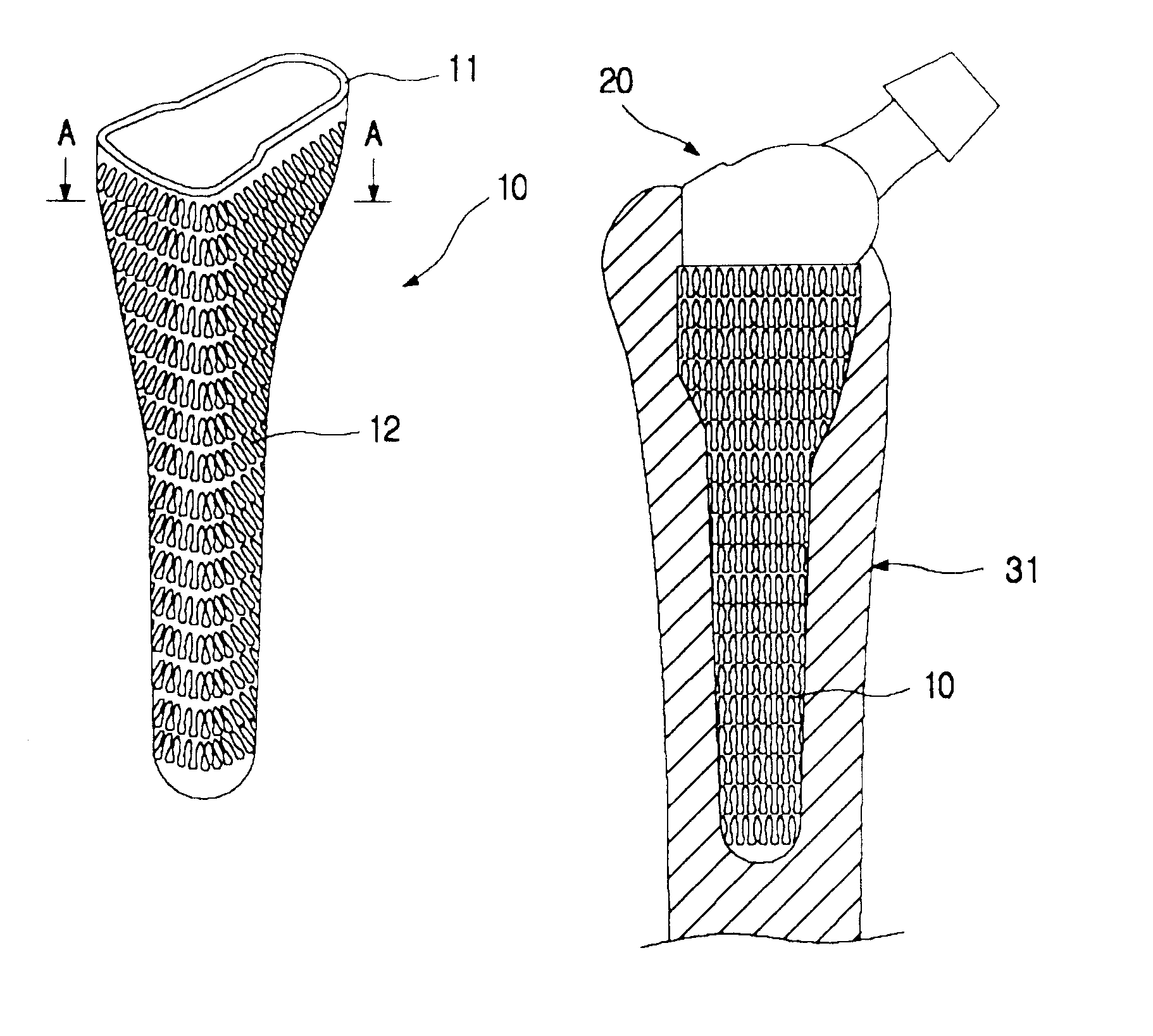
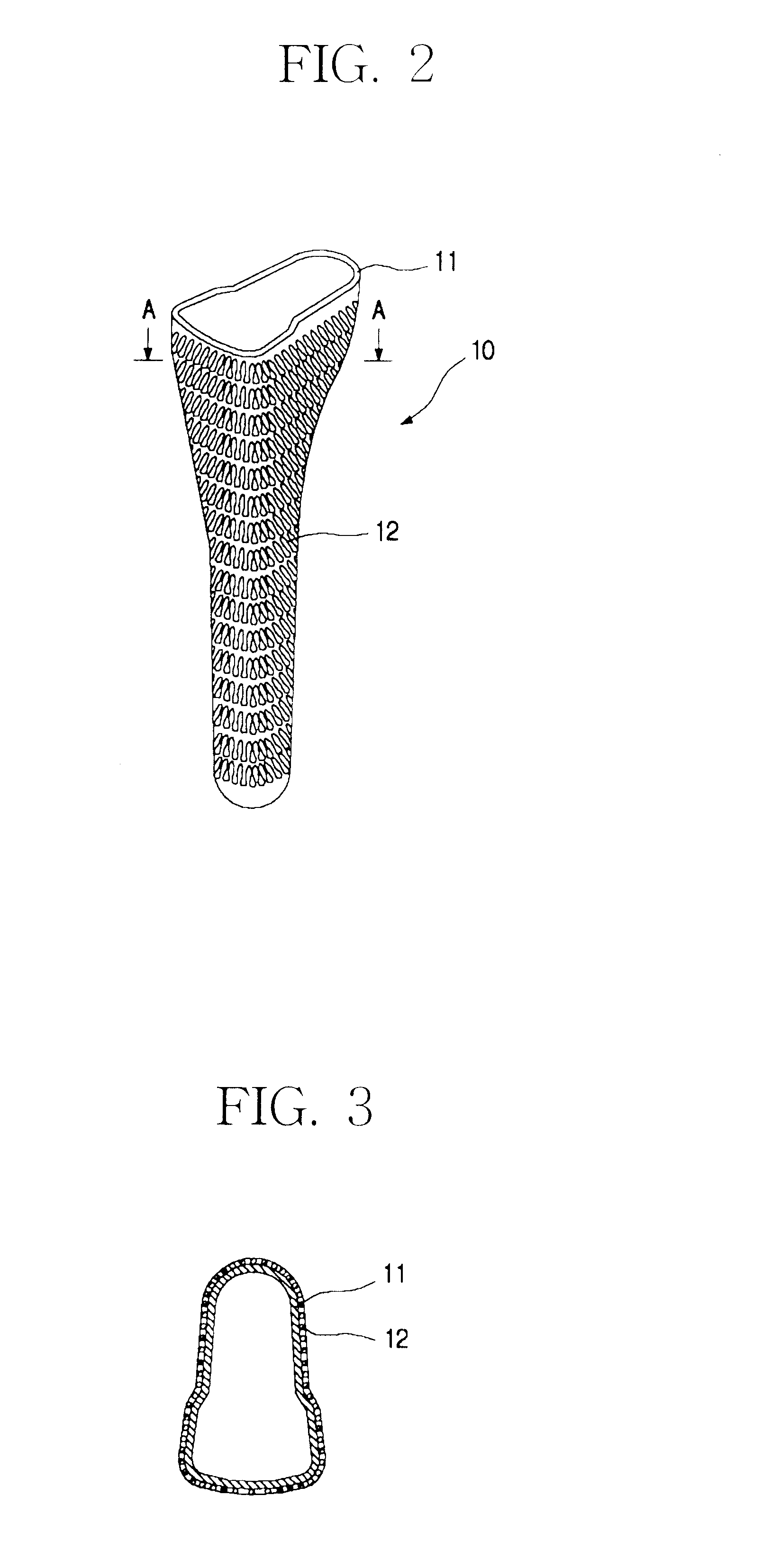
As can be seen in FIGS. 2 and 3, the metal jacket 10 for a cementless artificial joint stem according to a preferred embodiment of the invention is in the form adapted for enclosing the stem when a stem is inserted, or in the form of a bag. The metal jacket 10 is so formed that the stem may slide down vertically in the jacket when it is inserted and dimensioned in its diameter to match the outer diameter of a stem.

In addition, the metal jacket 10 is formed a little longer than the stem so that a predetermined space between the lower end of the stem and the lower end of the metal jacket remains to prevent the lower tip of the stem from touching the lower end of the metal jacket when the stem is placed in the metal jacket. The formation of such a prescribed space is to prevent a d...


PUM

PropertyMeasurementUnit
compressive forceaaaaaaaaaa
thicknessaaaaaaaaaa
adhesionaaaaaaaaaa

Abstract

The present invention is intended to provide a metal jacket for a cementless artificial joint stem, wherein shear force detrimental to the service life of an artificial joint can be markedly reduced and stress shielding phenomena can also be markedly relieved, due to the construction of the metal jacket which can be fixed to the bone and can enclose the surface of the stem so as to allow for the stem of artificial joint to slide vertically relative to the bone, and wherein osteolysis of a bone due to the infiltration of wear particles can be minimized by curbing the gap formation between the bone and the stem.To that end, there is provided according to the invention, a metal jacket for a cementless artificial joint stem, which jacket is so formed as to enclose at least a part of the cementless artificial joint stem 21, said stem with jacket being inserted longitudinally in the opening formed in the bone canal of a human body, and on the surface of which jacket surface-processed metal layer or metal wires 12 is formed so that the bone can make interlocking with the metal jacket as the bone gets on-growth onto the metal jacket.

Description

1. Field of the InventionThe present invention relates to a metal jacket for a cementless artificial joint stem, and particularly to a metal jacket for a cementless artificial joint stem, with said jacket secured to the bone in such a manner that the cementless artificial joint stem can slide relative to the bone and said jacket enclosing the surface of the cementless artificial joint stem. The invention also relates to a cementless artificial joint having the artificial joint stem enclosed in the jacket.2. Description of the Prior ArtGenerally, an artificial hip joint, for example, consists of an acetabular part and a femoral or thigh bone part, wherein the acetabular and femoral parts are made of either metal, plastic, or ceramic, independently.And the human femur is formed of the soft cancellous bone in the metaphyseal region and hard cortical bone in the diaphyseal region. Therefore, in order to insert an artificial joint into the human body, operation is conducted in such a way...

Claims


Application Information

Patent Timeline
Patent Type & Authority Patents(United States)
IPC IPC(8): A61F2/30A61F2/00A61F2/36A61F2/38A61F2/46A61F2/40
CPCA61F2/30907A61F2/30767A61F2/30965A61F2/36A61F2/3662A61F2/367A61F2/3676A61F2/38A61F2/40A61F2002/30113A61F2002/30125A61F2002/30136A61F2002/30172A61F2002/30332A61F2002/30372A61F2002/30619A61F2002/30685A61F2002/30738A61F2002/30784A61F2002/30822A61F2002/30902A61F2002/30906A61F2002/30909A61F2002/30919A61F2002/30929A61F2002/30971A61F2002/3611A61F2002/3625A61F2002/3631A61F2002/365A61F2002/3668A61F2220/0033A61F2230/0004A61F2230/0006A61F2230/0008A61F2230/0052A61F2250/0097A61F2310/00407A61F2002/30617A61F2002/30884A61F2/30
Inventor YONG, YOON SAN
Owner KOREA ADVANCED INST OF SCI & TECH
Why Eureka
Try Eureka