Image display

a technology of image display and sonic wave, which is applied in the field of image display, can solve the problems of difficult to provide stereoscopic images to a plurality of observers, and disadvantageously difficult to reduce or increase the length x of light arrival, so as to reduce the number of components, reduce the formation of interference fringes, and facilitate transmission

Inactive Publication Date: 2009-10-27
138 EAST LCD ADVANCEMENTS LTD +1
View PDF11 Cites 27 Cited by
  • Summary
  • Abstract
  • Description
  • Claims
  • Application Information

AI Technical Summary

Benefits of technology

[0012]The image display according to this aspect can change the length of arrival areas of light condensed on the positions of the observers in the first direction by changing the length of the transmissive portion and the shielding portion of the light emission control means in the first direction as hereinabove described. Therefore, the image display can reduce the length of the arrival areas of the light condensed on the positions of the observers and subdivide the arrival areas by reducing the length of the transmissive portion and the shielding portion of the light emission control means in the first direction and subdividing a set of the transmissive portion and the shielding portion. When there are a plurality of observers, therefore, the image display can condense the light received from the light source in the vicinity of the eyes of the plurality of observers respectively. Consequently, the image display can provide stereoscopic images to the plurality of observers by adding images having binocular parallax to the light incident upon the left and right eyes of the plurality of observers respectively. Further, the image display can increase the length of the arrival areas of the light condensed on the positions of the observers in the first direction through the same light emission control means by increasing the length of the transmissive portion and the shielding portion of the light emission control means in the first direction. When there are a plurality of observers located on different observational positions respectively, therefore, the image display can condense the light received from the light source in the vicinity of both eyes of the observers respectively through the same light emission control means. Consequently, the image display can provide different planar images (two-dimensional images) to the plurality of observers located on different observational positions respectively by adding different images to light advancing toward the observers located on different observational positions respectively. Thus, the image display according to this aspect can provide stereoscopic images to a plurality of observers and provide different planar images (two-dimensional images) to observers located on different observational positions respectively through the same light emission control means.
[0029]In the image display according to the aforementioned aspect, the lens portion of the lens formed to extend in the second direction is preferably provided in a state inclined by a prescribed angle with respect to a pixel train of the display panel extending in a direction substantially perpendicular to the first direction. According to this structure, the longitudinal direction of the lens portion and the direction of pixel arrangement of the display panel are inconsistent with each other, whereby the image display can inhibit the pixels of the display panel from re-interfering with light irradiated from the light source and incident upon the display panel with bright and dark stripes due to interference resulting from transmission through the lens portion provided on the lens. Consequently, the image display can suppress formation of interference fringes (moiré) on the display panel.

Problems solved by technology

Thus, it is difficult to subdivide or enlarge sets of the shielding portions 502a and the translucent portions 502b of the same liquid crystal panel 502, and hence it is disadvantageously difficult to reduce or increase the length X of the light arrival area 520 formed by the light passing through the translucent portions 502b of the same liquid crystal panel 502 in the direction A. Therefore, it is disadvantageously difficult to provide stereoscopic images to a plurality of observers by reducing the length X of the light arrival area 520 in the direction A shown in FIG. 18 thereby individually introducing light into the left and right eyes of the plurality of observers or to provide different planar images (two-dimensional images) to a plurality of observers located on different observational positions respectively by increasing the length X of the light arrival area 520 in the direction A shown in FIG. 18 through the same liquid crystal panel (light emission control means) 502.

Method used


Image

  • Image display
  • Image display
  • Image display

Examples


first embodiment

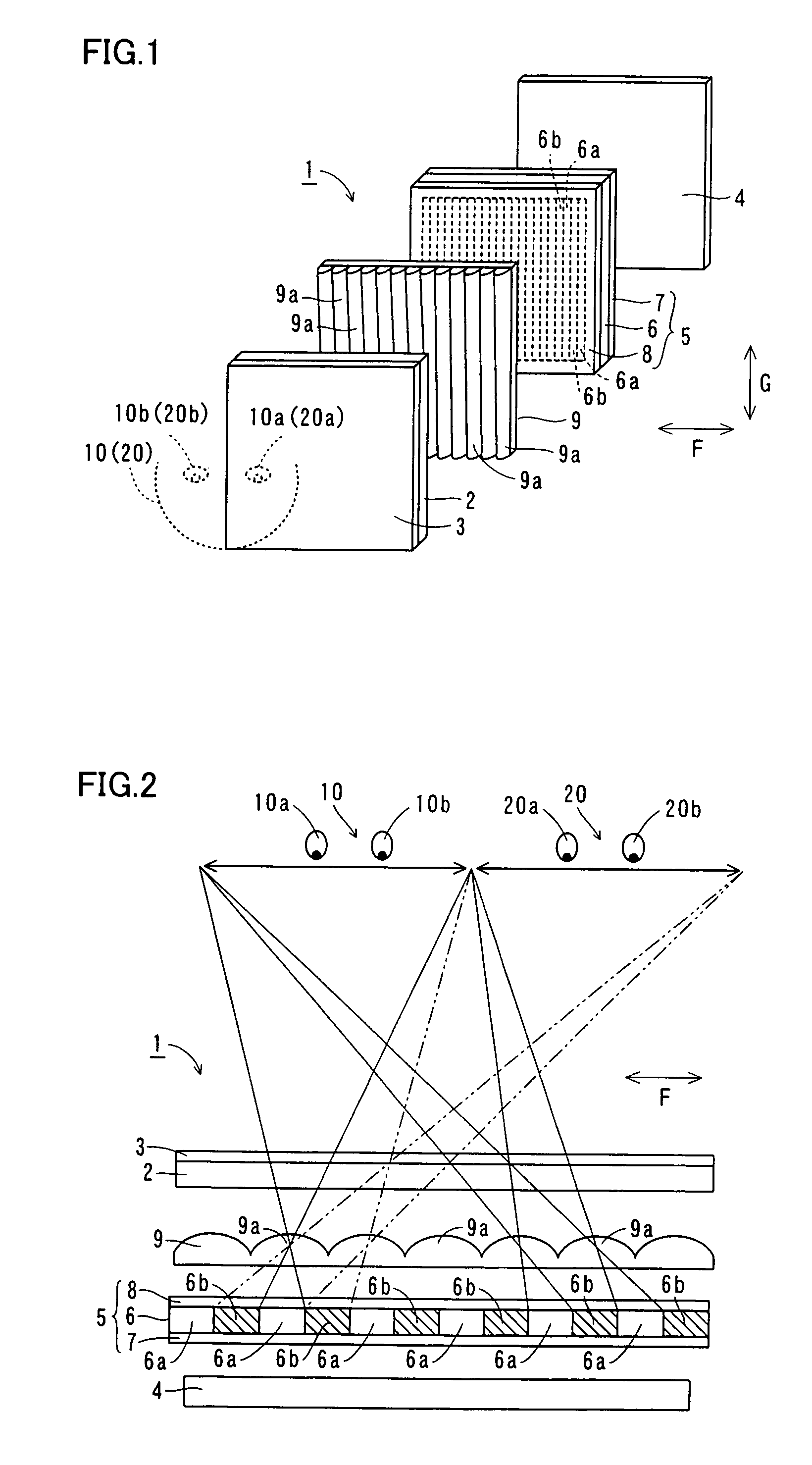
[0048]The structure of an image display 1 according to a first embodiment of the present invention is described with reference to FIGS. 1 to 4.

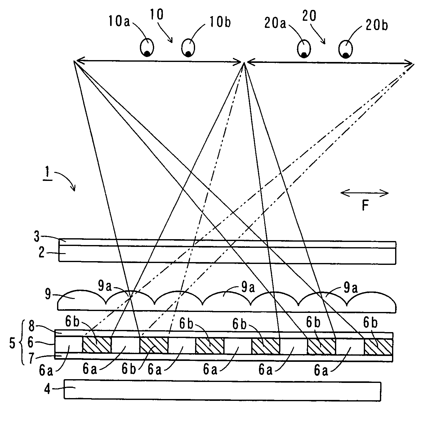
[0049]As shown in FIGS. 1 and 2, the image display 1 according to the first embodiment of the present invention comprises a display panel 2 for displaying images, a polarizing plate 3 mounted on a side of the display panel 2 closer to observers 10 and 20 and a backlight 4 for irradiating light toward the display panel 2.

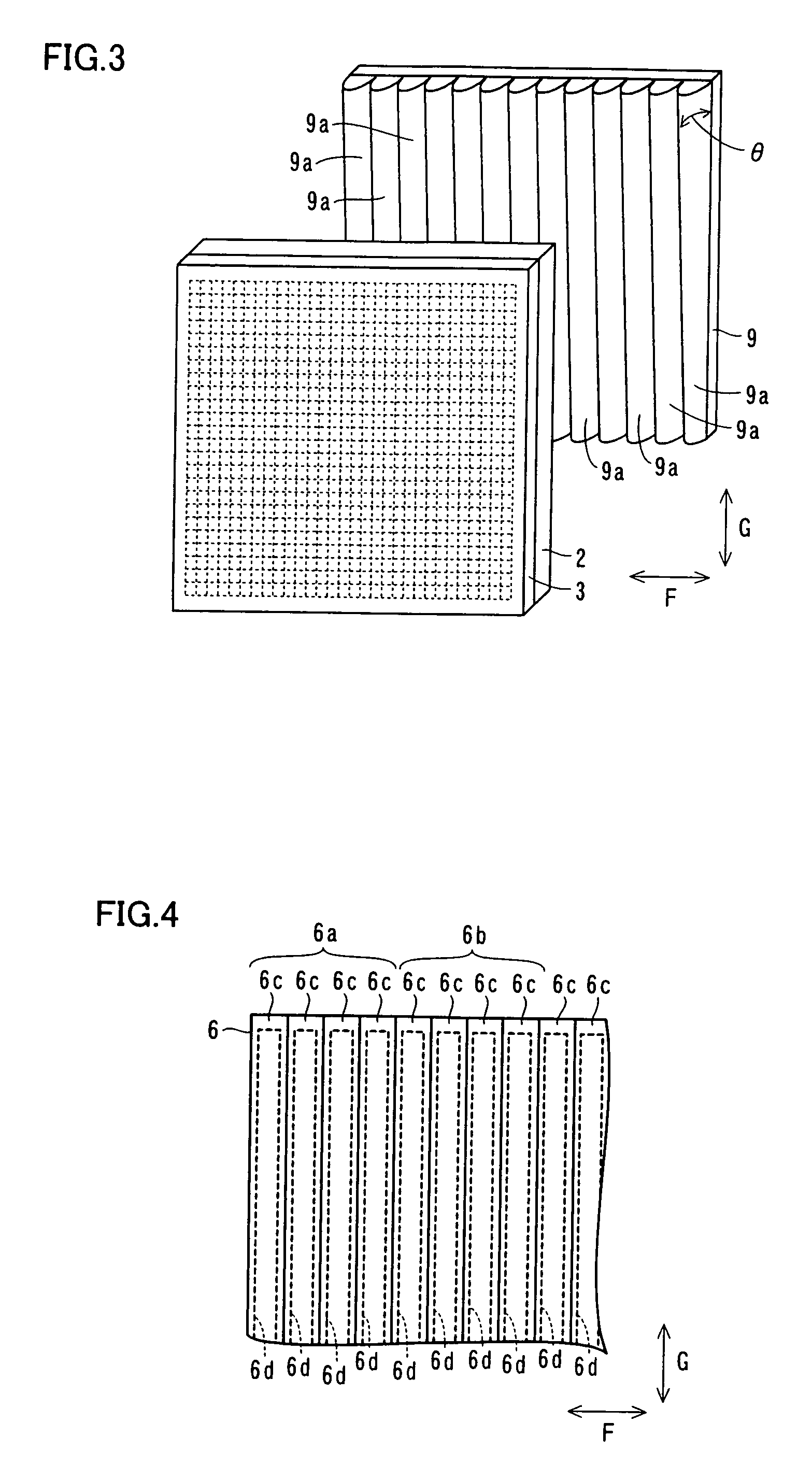
[0050]According to the first embodiment, a light emission control liquid crystal unit 5 is arranged on a side of the backlight 4 closer to the observers 10 and 20. The light emission control liquid crystal unit 5 is an example of the “light emission control means” in the present invention. As shown in FIG. 2, this light emission control liquid crystal unit 5 includes a light emission control liquid crystal panel 6 having transmissive areas 6a and shielding areas 6b for transmitting and blocking the light irradiated from the ba...

second embodiment

[0077]Referring to FIG. 12, an image display 100 according to a second embodiment of the present invention changes the position for displaying stereoscopic images following movement of the observational position of an observer, dissimilarly to the aforementioned first embodiment.

[0078]As shown in FIG. 12, the image display 100 according to the second embodiment comprises a position sensor 130 for sensing the position of an observer 10 and a control portion 140 for moving transmissive areas 6a for transmitting light and shielding areas 6b for blocking light by driving electrodes 6d of a light emission control liquid crystal panel 6 of a light emission control liquid crystal unit 5 in response to the position of the observer 10 sensed by the position sensor 130. The position sensor 130 is an example of the “position sensing means” in the present invention. According to the second embodiment, the image display 100 constitutes each transmissive area 6a of the light transmission control ...

third embodiment

[0082]Referring to FIG. 13, a lenticular lens portion 202a is integrated with a display panel 202 in an image display 200 according to a third embodiment of the present invention, dissimilarly to the aforementioned first embodiment. The remaining structure of the third embodiment is similar to that of the aforementioned first embodiment, and hence redundant description is not repeated.

[0083]As shown in FIG. 13, the image display 200 according to the third embodiment of the present invention comprises the display panel 202 for displaying images, a polarizing plate 3 mounted on a side of the display panel 202 closer to observers 10 and 20 and a backlight 4 for irradiating light toward the display panel 202.

[0084]According to the third embodiment, the display panel 202 is integrated with the lenticular lens portion 202a. Thus, the number of components can be reduced as compared with a case of providing the lenticular lens portion 202a and the display panel 202 independently of each oth...


PUM


Abstract

An image display including light emission controller provided with a transmissive portion and a shielding portion extending in a second direction intersecting with a first direction connecting the left and right eyes of an observer with each other for transmitting and blocking light irradiated from a light source respectively and capable of changing the length of the transmissive portion and the shielding portion in the first direction and a lens including at least one lens portion formed to advance the light received from the light source through the transmissive portion of the light emission controller in a prescribed direction and to extend in the second direction.

Description

BACKGROUND OF THE INVENTION[0001]1. Field of the Invention[0002]The present invention relates to an image display, and more particularly, it relates to an image display providing stereoscopic images etc. to observers.[0003]2.Cross-Reference to Related Applications[0004]The priority application No. JP2005-76195 upon which this patent application is based is hereby incorporated by reference.[0005]3. Description of the Background Art[0006]For example, Japanese Patent Laying-Open No. 10-161061 (1998) discloses a stereoscopic image display displaying three-dimensional stereoscopic images.[0007]As shown in FIG. 18, the stereoscopic image display 500 disclosed in Japanese Patent Laying-Open No. 10-161061 comprises a backlight 501, a liquid crystal panel 502, arranged on a light emission side of the backlight 501, having shielding portions 502a and translucent portions 502b, polarizing plates 503 and 504 opposed to each other to hold the liquid crystal panel 502 therebetween, a lenticular l...

Claims


Application Information

Patent Timeline
Patent Type & Authority Patents(United States)
IPC IPC(8): G02B27/22
CPCH04N13/0411H04N13/0418H04N13/047H04N13/0454H04N13/045H04N13/312H04N13/32H04N13/354H04N13/359H04N13/368B25D17/11B25D2222/72E02F3/966
Inventor HAMAGISHI, GORO
Owner 138 EAST LCD ADVANCEMENTS LTD
Why Eureka
Try Eureka