Cement jacket for a cemented artificial joint stem and artificial joint having the cement jacket

a cemented artificial joint and cement jacket technology, applied in the direction of shoulder joints, prostheses, osteosynthesis devices, etc., can solve the problems of accelerating bone osteolysis, gap between the femur and the stem, and serious drawbacks

Inactive Publication Date: 2003-02-25
KOREA ADVANCED INST OF SCI & TECH
View PDF17 Cites 27 Cited by
  • Summary
  • Abstract
  • Description
  • Claims
  • Application Information

AI Technical Summary

Benefits of technology

Further, it is provided, the outer surface of said cement jacket is formed with discharging paths in the longitudinal direction, so that the cement poured in the bone canal previously for the surgical purpose can be easily discharged upward at the time of inserting the jacket as well as enhancing anchorage of the new cement mantle with the jacket.
In the case of using an artificial joint equipped with a cement jacket for the stem according to the invention, predominantly a compressive force comes into action between the bone and the cement jacket to suppress the formation of fibrous tissue membrane, to activate or fortify the bone, and to reduce the shear stress detrimental to the bone at the interface between the bone and the cement jacket and turn the stress into a compressive force beneficial to the bone. Such enhanced compressive force strengthens the bone and acts to minimize the osteolysis of bone due to the infiltration of wear particles by deterring the formation of gap between the bone and the cement mantle. Also, it is known that the shear stress at the cement-bone interface invokes micromotion at that interface and eventually will develop soft-tissue membrane at that interface, which is detrimental to the fixation of the stem. The said jacket definitely will reduce this kind of undesirable shear stress at the bone-cement interface by increasing the compressive stress which is beneficial as aforementioned.
Furthermore, the cement jacket for an artificial joint stem according to the invention has the advantage that the generation of wear particles from frictional contact with the stem can be minimized by coating a film of plastic resistant to wearing-out, preferably polyethylene film on the inner surface of the jacket.
Still further, the cement jacket according to the invention has the advantage that direct contact between the femur and the stem is prevented by providing a strong and uniform cement layer and breakage of a jacket due to the vertical sag of a stem is prevented by securing a space between the end of the jacket and the end of the stem.

Problems solved by technology

As hinted before, while the artificial joint implanted in a human body is used, the cement layer used for fixing the stem of the artificial joint frequently falls apart from the femur, causing a gap between the femur and the stem.
Then the wear particles produced by the sliding action between the acetabular cup and the femoral head may penetrate into the gap or effective joint space formed between the bone and the stem and accelerate osteolysis of the bone as a serious drawback.
Further, for an artificial joint according to the conventional art, a substantial part of the vertical force is transferred to the lower side and therefore the upper side of a femur is depleted of stress and so associated with the defect of weakening due to stress shielding.
Moreover, the cement layer formed during an operation for a cemented implant such as an Exeter stem, exhibits a poor mechanical property (for example, the tensile strength amounting to less than a half of the normal value) and so has the risk of easy breakage.
Additionally, a risk of mutual contact of the stem and the bone exists due to the difficulty in securing a uniform thickness of cement, which may provide a passage of wear particles from the acetabulum cup into the femoral bone-cement interface and invoke osteolysis at the site.
There is also a possibility of break at the tip portion of the stem, when the stem sinks under a vertical load.
Also, it is known that the shear stress at the cement-bone interface invokes micromotion at that interface and eventually will develop soft-tissue membrane at that interface, which is detrimental to the fixation of the stem.

Method used


Image

  • Cement jacket for a cemented artificial joint stem and artificial joint having the cement jacket
  • Cement jacket for a cemented artificial joint stem and artificial joint having the cement jacket
  • Cement jacket for a cemented artificial joint stem and artificial joint having the cement jacket

Examples


Embodiment Construction

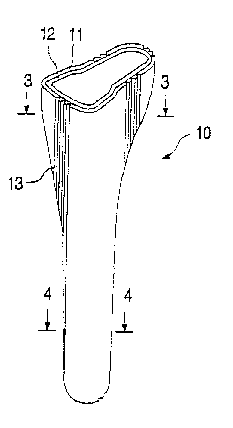
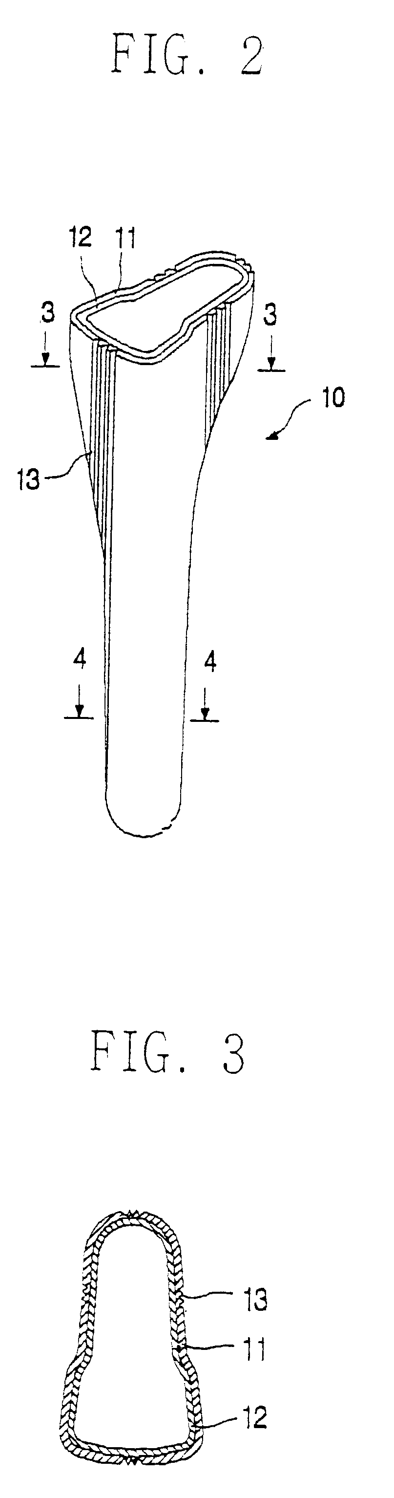
A preferred embodiment of a cement jacket for a cemented artificial joint stem and an artificial joint equipped with that cemented jacket will be described in detail below by referring to accompanying drawings.

As can be seen in FIGS. 2 to 4, the cement jacket 10 for cemented artificial joint stem according to a preferred embodiment of the invention is in the form adapted for enclosing the stem when the stem is inserted, or in the form of a bag, preferably with tight fit between the jacket and the stem, so that small vertical sliding movement of the stem may be allowed while lateral motion of the stem within the jacket 10 is prevented.

The cement jacket 10 is formed a little longer than the stem so that a predetermined space between the lower end of the stem and the lower end of the jacket remains to prevent the lower tip of the stem from touching the lower end of the jacket when the tip is placed in the jacket. The formation of such a prescribed space is to prevent a damage on the ce...


PUM

PropertyMeasurementUnit
resistanceaaaaaaaaaa
adhesive strengthaaaaaaaaaa
physical binding strengthaaaaaaaaaa

Abstract

A cement jacket for a cemented artificial joint stem, the cement jacket including a main body with a hollow interior and an open upper end for receiving and enclosing at least a part of a stem of an artificial joint, the cement jacket being shaped and adapted for longitudinal insertion in an opening formed in a bone canal of a human body, the cement jacket being made of cement and reinforced by imbedded wire or fiber and having an inner surface coated with a plastic film having a high resistance to abrasion, and the outer surface of the cement jacket is formed with discharging paths in the longitudinal direction so that excessive cement paste previously poured into the bone canal for the surgical purpose can be easily discharged upward at the time of inserting the jacket.

Description

1. Field of the InventionThe present invention relates to a cement jacket for a cemented artificial joint stem, and particularly to a cement jacket for a cemented artificial joint stem, with jacket secured to the bone in such a manner that the artificial joint stem can slide relative to the bone and said jacket enclosing the surface of the artificial joint stem. The invention also relates to an artificial joint having the artificial joint stem enclosed in the cement jacket.2. Description of the Prior ArtGenerally, an artificial hip joint, for example, consists of an acetabular part and a femoral or thigh bone part, wherein the acetabular and femoral parts are made of either metal, plastic, or ceramic, independently.The human femur is formed of the cortical bone containing soft marrow. Therefore, in order to insert an artificial joint into the human body, operation is conducted in such a way that the bone canal is reamed out, the stem of artificial joint is inserted and finally ancho...

Claims


Application Information

Patent Timeline
Patent Type & Authority Patents(United States)
IPC IPC(8): A61F2/30A61F2/00A61F2/36A61F2/38A61F2/46A61F2/40A61B17/56A61L27/00
CPCA61F2/30907A61B2017/8813A61F2310/00952A61F2/30965A61F2/36A61F2/3662A61F2/367A61F2/3676A61F2/38A61F2/40A61F2002/30113A61F2002/30125A61F2002/30172A61F2002/30332A61F2002/30372A61F2002/30619A61F2002/30685A61F2002/30738A61F2002/30822A61F2002/30828A61F2002/30902A61F2002/30919A61F2002/30929A61F2002/30971A61F2002/3611A61F2002/3625A61F2002/3631A61F2002/365A61F2002/3668A61F2002/4631A61F2220/0033A61F2230/0006A61F2230/0008A61F2230/0052A61F2250/0097A61F2/30767A61F2002/30617A61F2002/30884A61F2/30
Inventor YOON, YONG-SAN
Owner KOREA ADVANCED INST OF SCI & TECH
Why Eureka
Try Eureka