
Ink cartridge

a technology of ink cartridges and ink cartridges, applied in the field of ink cartridges, can solve the problems of poor printing, shortening the time during which ink can be continuously used, and wasting ink,

Inactive Publication Date: 2003-01-14
BROTHER KOGYO KK
View PDF3 Cites 63 Cited by
  • Summary
  • Abstract
  • Description
  • Claims
  • Application Information

AI Technical Summary

Benefits of technology

This solution allows for the efficient use of ink, maintaining high-quality printing by ensuring proper meniscus formation in the ink jet print head nozzles, reducing ink wastage, and extending the continuous usage time of the printer.

Problems solved by technology

Since all the ink filled in the ink pack 109a cannot be used up, the ink is wasted or the time during which the ink can be continuously used, becomes short.
Since the range where appropriate negative pressures can be applied only using the upper supporting spring 151 is small with respect to the amount of ink usage, it is difficult to maintain appropriate negative pressures from the start to the end of the ink usage.
As appropriate negative pressures are not maintained, meniscuses (curved surfaces) of ink liquid are not properly formed in the nozzles of the ink jet print head, resulting in poor printing, such as excessive amounts of ink droplets ejected, splattered inks, ink blurred, and no ink ejected.
Consequently, the running costs of the printer are cut down and the time during which the printer can continuously be used becomes long.
Since the appropriate negative pressures can be maintained from the start to the end of the ink usage using two plate springs, meniscuses (curved surfaces) of ink liquid are properly formed in the nozzles of the ink jet print head and poor printing, such as excessive amounts of ink droplets ejected, splattered inks, ink blurred, and no ink ejected will not occur.
Consequently, the running costs of the printer are cut down and the time during which the printer can continuously be used becomes long.

Method used


Image

  • Ink cartridge
  • Ink cartridge
  • Ink cartridge

Examples


second embodiment

the invention will be described in detail below. The structure common to the ink cartridges 8, 9 will be described in detail, taking the small ink cartridge 9 as an example.

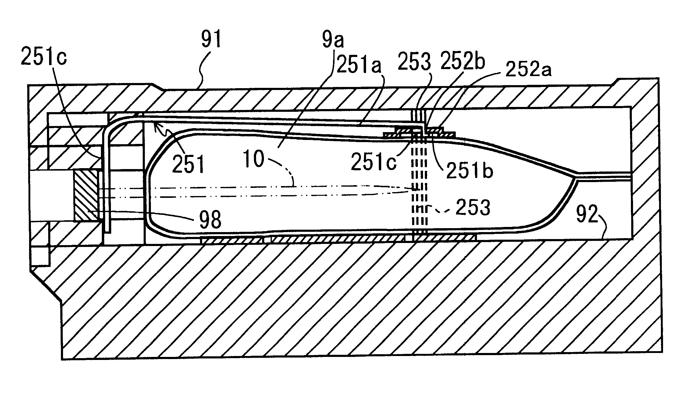
FIG. 16A is a plan view of a supporting spring 251 and an engagement portion 252 before they are engaged with each other. FIG. 16B is a plan view of the supporting spring 251 and the engagement portion 252 engaged with each other. FIG. 20 is a schematic sectional view of the small ink pack 9 taken on line XI--XI of FIG. 6, illustrating a state that the small ink pack 9a is filled up with ink The supporting spring 251 and the engagement portion 252 will be described below with reference to FIGS. 16 and 20.

As shown in FIG. 16A, the supporting spring 251 is formed by punching and bending an elastic plate spring made of a thin plate of stainless steel. The supporting spring 251 has a substantially C-shaped outer portion 251a and a fixing portion 251c. The fixing portions 251c are a pair of protruding portions bent so...


PUM


Abstract

The invention provides a ink cartridge for supplying ink, including an ink pack formed from a flexible bag to seal liquid ink therein, a cartridge body having an ink pack housing therein, an extraction opening having a rubber plate into which a hollow ink extracting needle is inserted, an upper supporting spring movably supported with one end thereof by the cartridge body and affixed to the upper surface of the ink pack, and a lower supporting plate affixed to the lower surface of the ink pack and the lower surface of the cartridge body. A pair of the upper supporting spring and the lower supporting spring urges / pulls so that the volume of the bag of the ink pack is enlarged.

Description

1. Field of InventionThe invention relates to an ink cartridge for use with a printing apparatus capable of performing printing via a liquid ink.2. Description of Related ArtIn an ink jet print head for use with a printing apparatus, such as an ink jet printer, a curved surface (meniscus) of ink liquid needs to be formed in ink nozzle openings of the ink jet print heads for printing to be performed properly. For the meniscus to be formed for proper printing, appropriate negative pressures need to be applied and maintained while ink is supplied.A compact and lightweight ink cartridge exists that is used for a portable printer and the like, having a structure such that ink contained in a flexible bag of an ink pack is supplied to a print head from the ink pack through an ink extracting needle inserted into the ink pack. The ink cartridge having the flexible ink pack may maintain negative pressures therein due to the rigidity and strength of the bag.However, to certainly apply and main...

Claims


Application Information

Patent Timeline
Patent Type & Authority Patents(United States)
IPC IPC(8): B41J2/175
CPCB41J2/17503B41J2/17523B41J2/17513
Inventor SHIMIZU, SEIJI
Owner BROTHER KOGYO KK
Learn More