BIST circuit for variable impedance system

a variable impedance system and circuit technology, applied in logic circuit coupling/interface arrangement, pulse technique, instruments, etc., can solve the problems of system performance suffer, too much or too little strength, and the mismatch between the output driver of the sram and the characteristic line impedance of the system is very undesirabl

Inactive Publication Date: 2003-01-21
INT BUSINESS MASCH CORP
View PDF7 Cites 41 Cited by
  • Summary
  • Abstract
  • Description
  • Claims
  • Application Information

AI Technical Summary

Problems solved by technology

Since some output drivers have only one impedance rating, an output driver driving a load other than the one it is designed for would result in too much or too little of the strength needed.
Consequently, such a system would suffer in performance from factors such as slow downs of a high performance system and / or dissipation of dc power.
The mismatch between the SRAM output driver and the characteristic line impedance of the system is very undesirable in high performance and small signal applications, such as cache to processor I / O interfaces.
Furthermore, if a separate part was designed for the many different load strengths across different systems, the costs may become expensive.
However, as the impedance tolerance of such drivers varies, the system's performance degrades and testing such drivers has proved a difficult proposition.
The need for on-chip circuitry to test the variable impedance circuit arises from the inability to test this circuit during manufacturing.

Method used


Image

  • BIST circuit for variable impedance system
  • BIST circuit for variable impedance system
  • BIST circuit for variable impedance system

Examples


Embodiment Construction

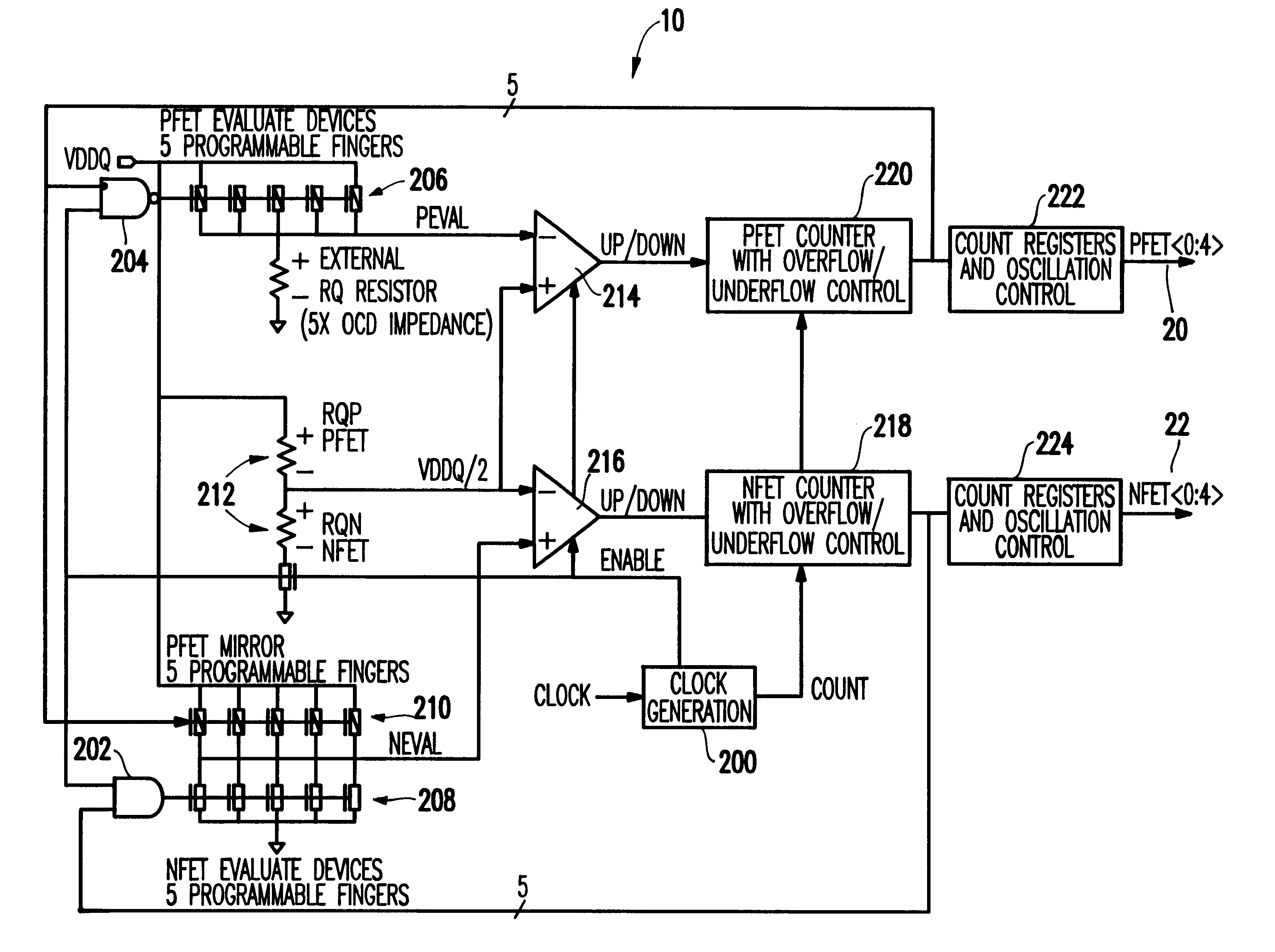
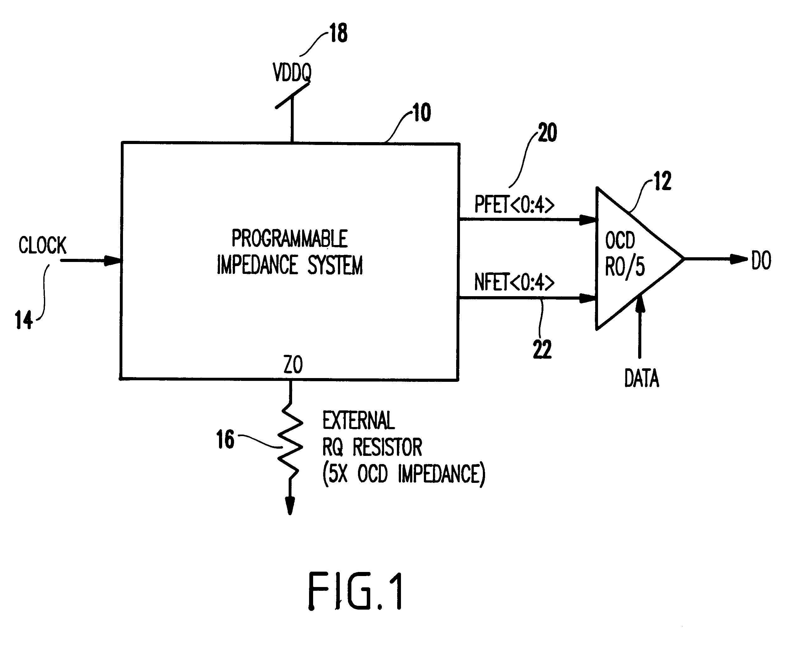
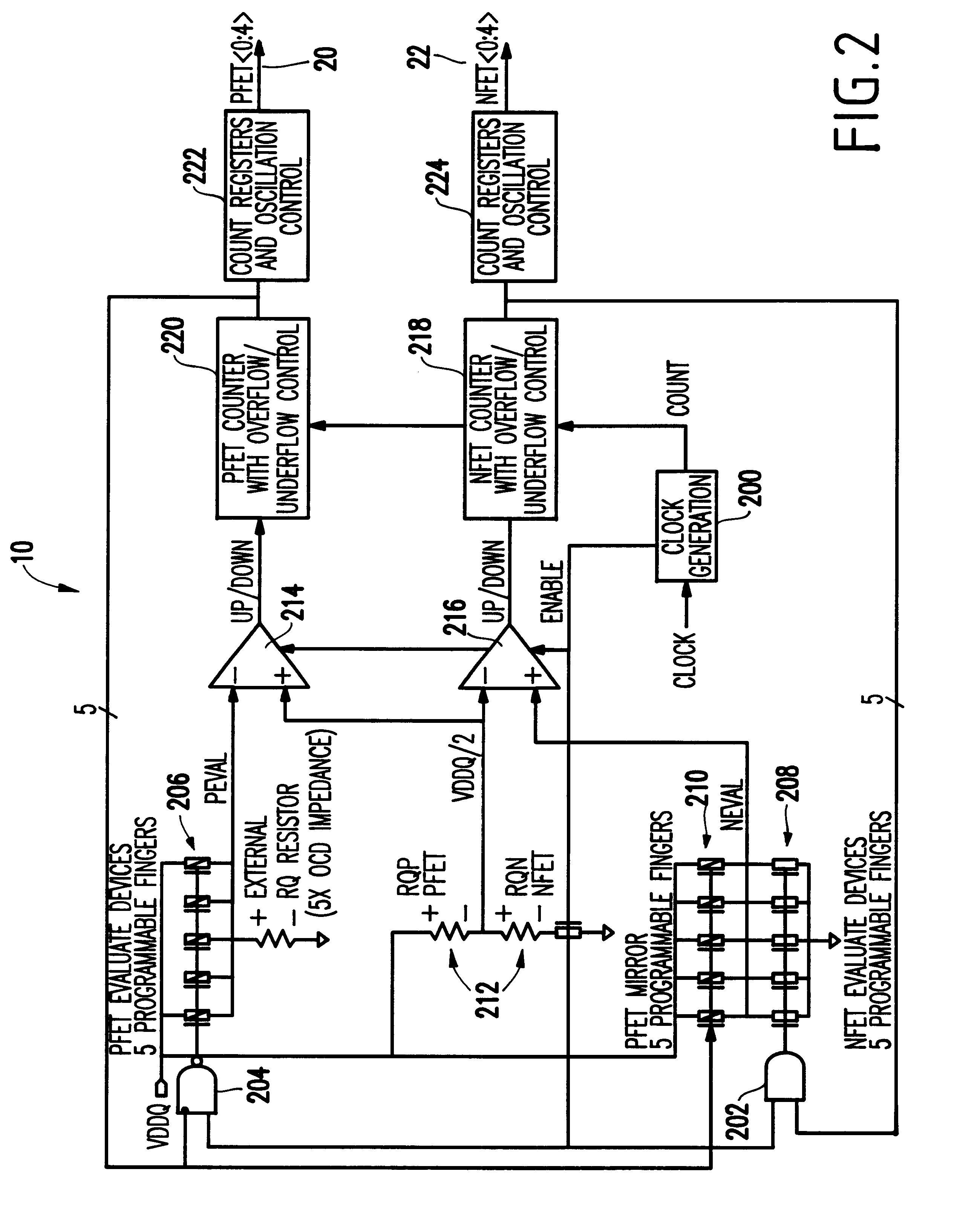
In general terms, the invention is a programmable impedance driver that includes two sets of impedance devices, two primary counters and two test counters. The primary counters selectively activate individual ones of the impedance devices to vary an overall impedance of the driver during normal operation and the test counters verify the counting operation of the primary counters during manufacturing testing of the driver. Therefore, the built-in self-test (BIST) aspect of the invention easily detects if one of the counters will become stuck during normal usage.

The invention also includes two comparators receiving signals from the primary counters and the test counters that determine if respective pairs of the primary counters and the test counters have identical counts. A test output pin is connected to the comparators and outputs a signal indicating a functionality of the primary counters.

The sets of impedance devices include p-type field effect transistors (PFET) and n-type field ...


PUM


Abstract

Disclosed is a programmable impedance driver that includes two sets of impedance devices, two primary counters and two test counters. The primary counters selectively activate individual ones of the impedance devices to vary an overall impedance of the driver and the test counters verify the counting operation of the primary counters during manufacturing testing of the driver. Therefore, the built-in self-test (BIST) aspect of the invention easily detects if one of the counters will become stuck during normal usage.

Description

1. Field of the InventionThe present invention generally relates to test systems for integrated circuits and more particularly to a built in self test circuit for a variable impedance system.2. Description of the Related ArtIn electrical systems, output drivers are used to drive input / output (I / O) devices or similar loads. Each output driver is set up with a certain voltage / impedance that matches the strength of the transmission line and I / O device being driven by that specific driver. Thus, I / O devices with a low drive strength would need an output driver with a high impedance, and high strength I / O devices require a low impedance driver. Since some output drivers have only one impedance rating, an output driver driving a load other than the one it is designed for would result in too much or too little of the strength needed.In addition, output driver impedance variations as a result of supply voltage, temperature, and process variations may be as high as 100% of the desired impeda...

Claims


Application Information

Patent Timeline
Patent Type & Authority Patents(United States)
IPC IPC(8): G01R31/28G01R31/3187G01R31/3185
CPCG01R31/2891G01R31/3187G01R31/318527
Inventor BRACERAS, GEORGE MBURNS, STEVENHANSEN, PATRICK R.PILO, HAROLD
Owner INT BUSINESS MASCH CORP
Why Eureka
Try Eureka