Direct digital synthesizer

a digital synthesizer and digital synthesizer technology, applied in the direction of automatic control, instruments, computing, etc., can solve the problems of increasing cost, slow and complex circuit, and increasing complexity of circui

Inactive Publication Date: 2003-03-25
LUCENT TECH INC +1
View PDF12 Cites 15 Cited by
  • Summary
  • Abstract
  • Description
  • Claims
  • Application Information

AI Technical Summary

Problems solved by technology

This generality makes the circuit slow and complex.
Although pipelined adder circuits increased the speed by which the control word was added to the current count, the circuit was made even more complex, which incre

Method used


Image

  • Direct digital synthesizer
  • Direct digital synthesizer
  • Direct digital synthesizer

Examples


Embodiment Construction

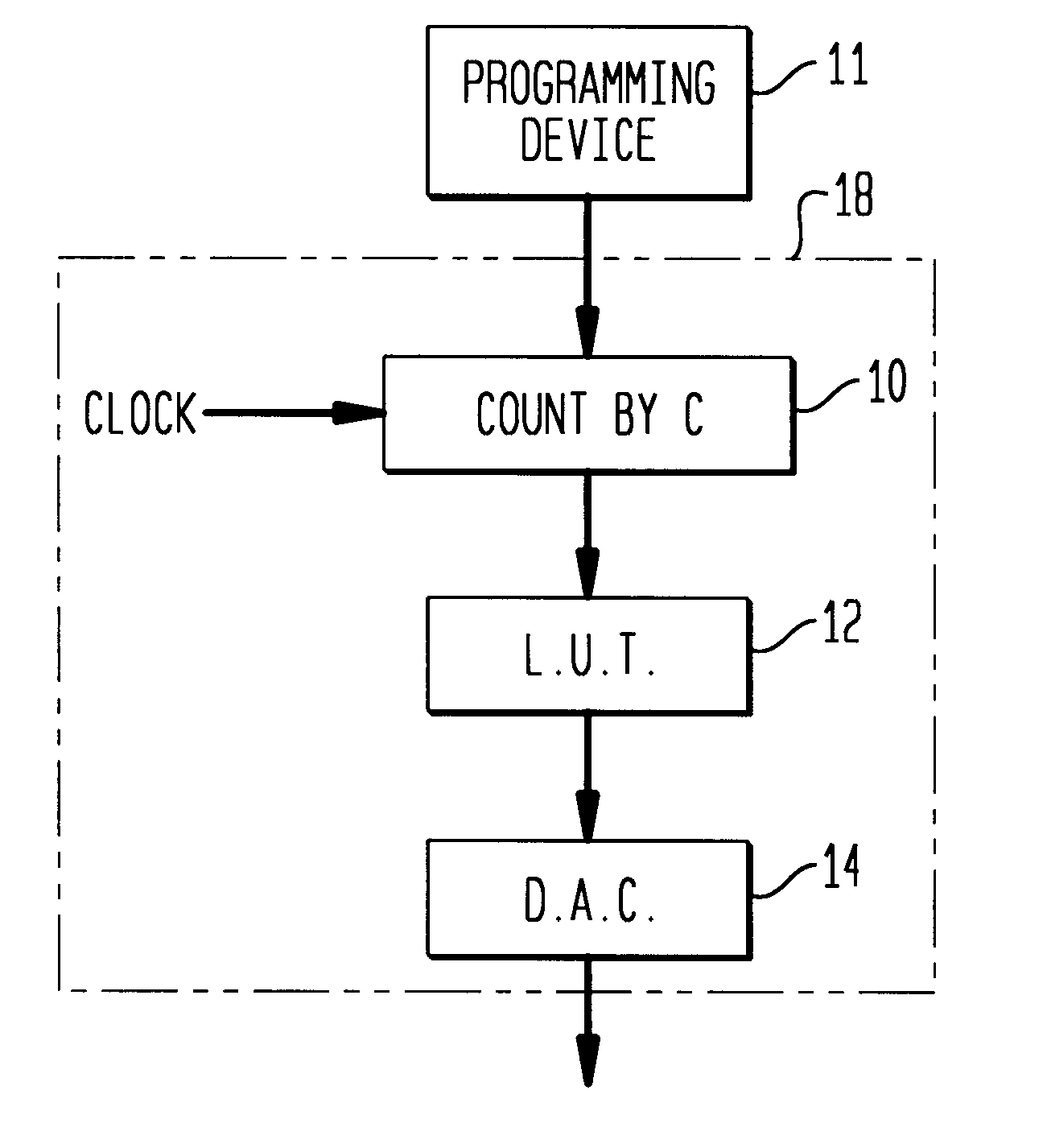
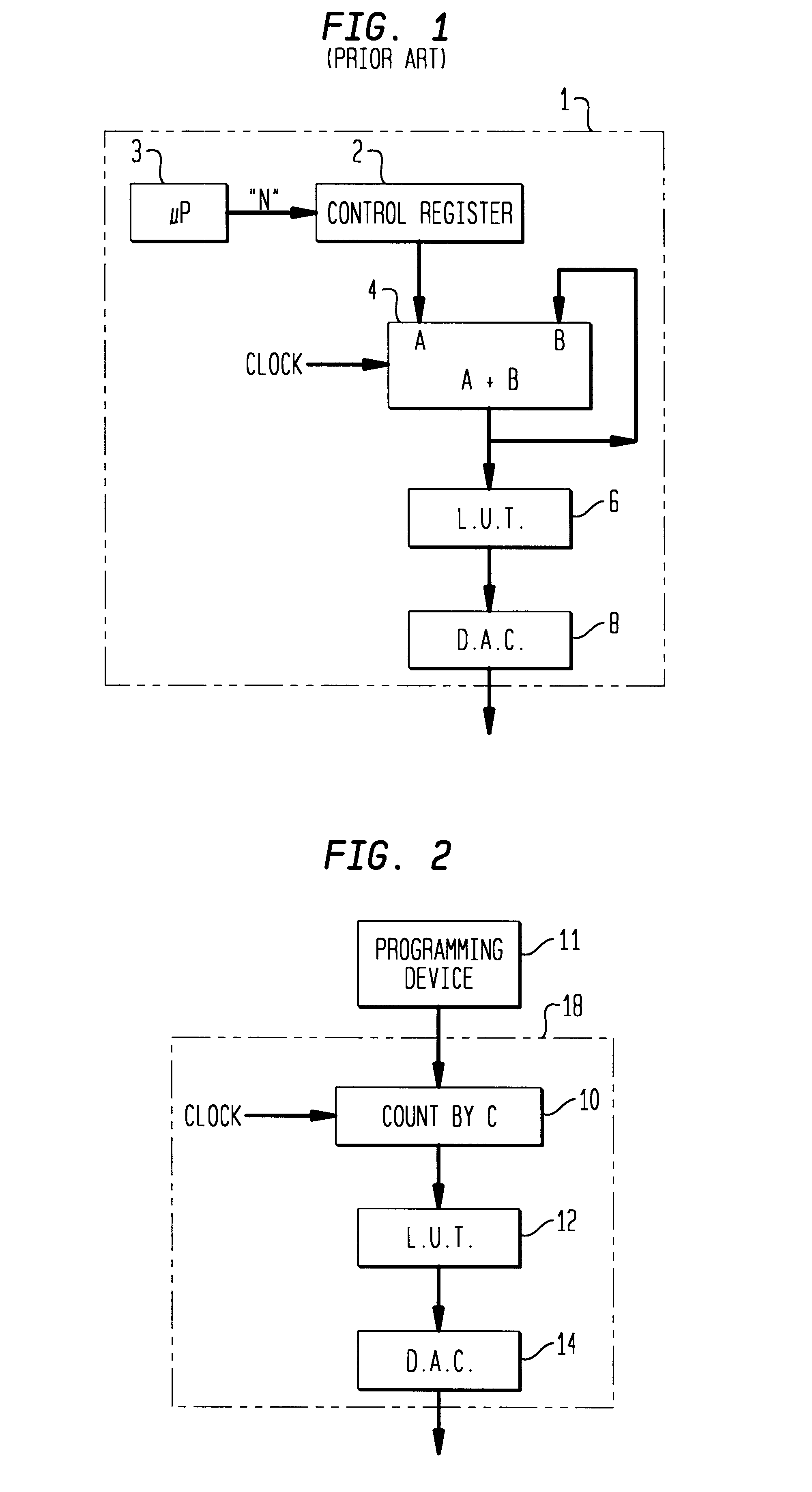
The present invention is directed to a digital synthesizer 18 of FIG. 2, and preferably a direct digital synthesizer which can operate at a very high frequency. As shown in FIG. 2, the digital synthesizer 18 includes a counter 10, which, upon receiving a clock input, counts by a predetermined fixed increment "C" (wherein "C" is an integer); a memory 12, such as a programmable read only memory (PROM), which stores and outputs digital waveform values upon receiving an input from the counter 10; and a digital-to-analog converter 14 which converts the digital waveform values output from the memory 12 into an analog waveform.

Preferably, the counter 10 is a non-volatile reconfigurable complex programmable logic device (CPLD) IC. A programming device 11, external to the direct digital synthesizer 18 and capable of incrementing by the predetermined fixed increment "C", preferably loads the circuit configuration of the counter 10 of the digital synthesizer 18. Such a counter 10 operates at a...


PUM


Abstract

A digital synthesizer includes a memory containing values representing amplitudes of a signal such as a sinewave, a digital/analog converter for converting outputs from the memory into an analog signal, and a counter for counting by a predetermined fixed increment, which operates at a high frequency to enable the generation of very precise frequency waveforms. The digital synthesizer has many practical applications including the generation of precise signals to extract information from input radio frequency signals, the obtaining of a precise frequency from a low-cost clock, and the use as a component of a FSK modulator to permit selection between signals of multiple frequencies without any phase discontinuity. Finally, the digital synthesizer can be used in combination with an 8-bit memory, to generate a 10-bit input to a digital-to-analog converter.

Description

1. Field of the InventionThe present invention relates to an improved direct digital synthesizer.2. Description of the Related ArtDirect digital synthesis (DDS) is an electronic circuit technique used to generate periodic waveforms. A direct digital synthesizer generates a stream of digital data which is transformed into an analog waveform with a digital-to-analog converter (DAC). A direct digital synthesizer operates by clocking a binary accumulator (typically greater than or equal to 24 bits) at a high frequency (for example, >100 Mhz).The accumulator is essentially an adder circuit with one input and one output. At every clock signal, the input value is added to the current output value and the output of the accumulator assumes a new sum. The input, usually referred to as a control word, specifies the magnitude of the count increment. If the control word is 250, the accumulator will count in a 0, 250, 500, 750, 1000 . . . sequence until it rolls over and continues.A known dire...

Claims


Application Information

Patent Timeline
IPC IPC(8): G06F1/02G06F1/03H03B28/00H03L7/23
CPCG06F1/0321H03L7/23
Inventor JOHNSON, ROBERT EVEREST
Owner LUCENT TECH INC
Why Eureka
Try Eureka