

Retaining device
a technology of retaining device and locking bar, which is applied in the direction of supporting structure mounting, casing/cabinet/drawer details, electrical apparatus casing/cabinet/drawer, etc., can solve the problems of difficult to correctly remove and replace the locking bar, the process of trying to screw or unscrew the card or cover plate is awkward, and the risk of damag
- Summary
- Abstract
- Description
- Claims
- Application Information
AI Technical Summary
Problems solved by technology
Method used
Image

Examples
Embodiment Construction
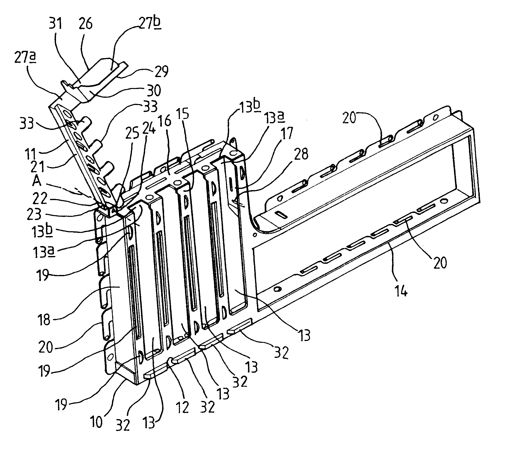
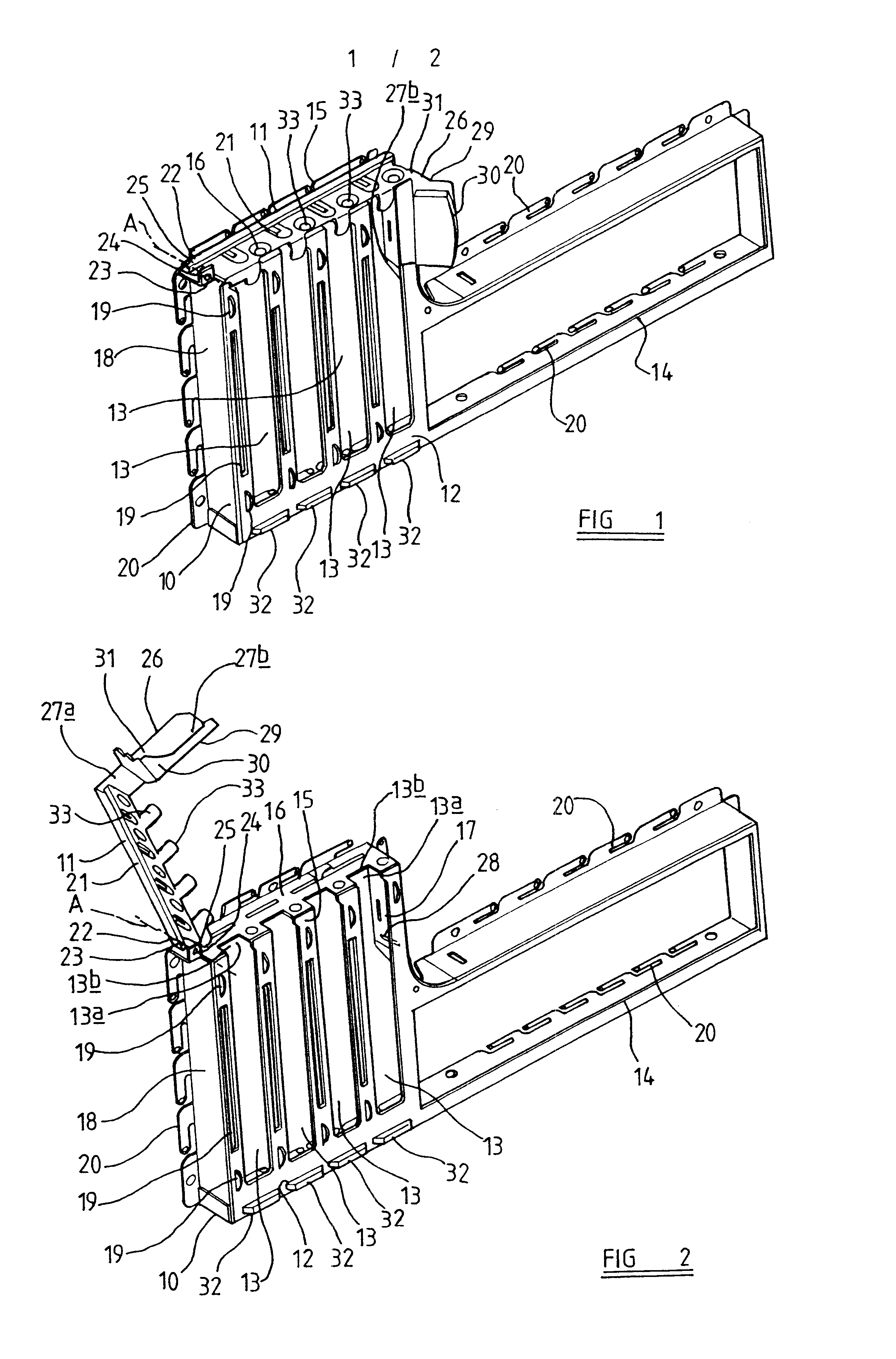
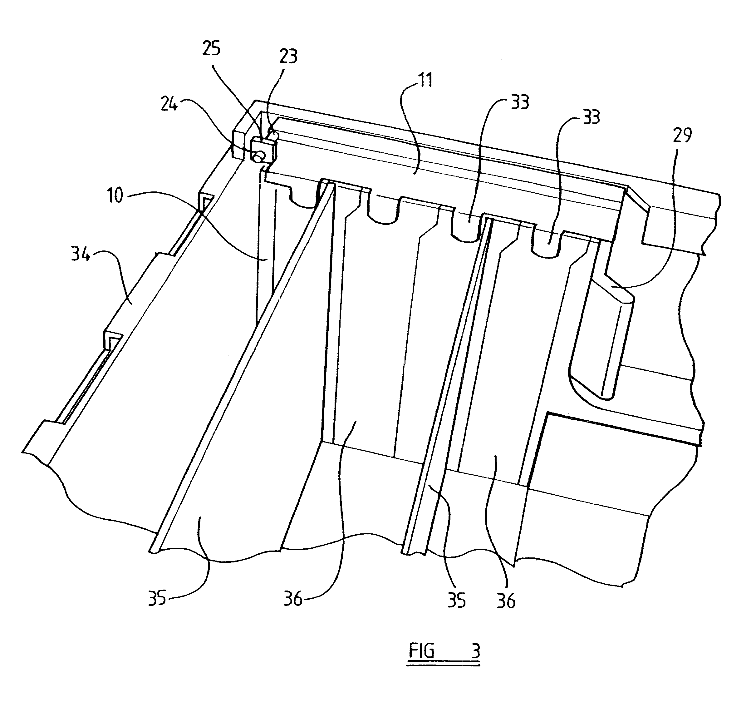
This invention relates to a retaining device for a card slot assembly, and to a card slot assembly, particularly but not exclusively for provision as part of a personal computer chassis
BACKGROUND TO THE INVENTION
To enable a computer, particularly a personal computer, to be provided with additional cards to perform desired functions, it is known to provide the computer chassis with a card slot assembly. The card slot assembly conventionally comprises a plurality of generally parallel slots each of which receive one end of a card, to provide an external connection for the card and to physically hold one end of the card in place. Where a slot is not in use, a cover plate provided which closes the slot and which is attached to the card slot assembly, to prevent the ingress of dirt and other foreign bodies into the computer case.
To hold the card in place relative to the card slot assembly, it is necessary to provide some kind of retaining device. It is known to provide a threaded hole co...
PUM
 Abstract
Description
Claims
Application Information