System and method for detecting an intruder using impulse radio technology

a technology of impulse radio and intruder detection, applied in the security field, can solve the problems of inability to detect an intruder by the intrusion detection system, easy jamming, hacked, spoofed or otherwise defeated by intruders, and is essentially spoofproof or very difficult for an intruder to defea

Inactive Publication Date: 2003-09-02
HUMATICS CORP
View PDF23 Cites 130 Cited by
  • Summary
  • Abstract
  • Description
  • Claims
  • Application Information

AI Technical Summary

Problems solved by technology

Unfortunately, if the intruder penetrates the fence without triggering the alarm then detection of that intruder by the intrusion detection system is unlikely.
Unfortunately, all of these intrusion detection systems and other well known intrusion detection systems can be easily jammed, hacked, spoofed or otherwise defeated by intruders.
Accordingly, there is a need for an intrusion detection system and method that is essentially spoof-proof or very difficult for an intruder to defeat.
Such codes are commonly referred to as time-hopping codes or pseudo-noise (PN) codes since their use typically causes inter-pulse spacing to have a seemingly random nature.
band. It can also be observed from FIG. 2A that impulse transmission systems typically have very low average duty cycles, resulting in average power lower than peak
As the number of coincidences increases, the propensity for data errors increases.
Generally, keeping the number of pulse collisions minimal represents a substantial attenuation of the unwanted signal.
Such `random-like` codes are attractive for certain applications since they tend to spread spectral energy over multiple frequencies while having `good enough` correlation properties, whereas designed codes may have superior correlation properties but possess less suitable spectral properties.
Impulse radio systems operating within close proximity to each other may cause mutual interference.
While coding minimizes mutual interference, the probability of pulse collisions increases as the number of coexisting impulse radio systems rises.
Additionally, various other signals may be present that cause interference.
However, when the transmitted impulse signal is coded and the impulse radio receiver template signal 506 is synchronized using the identical code, the receiver samples the interfering signals non-uniformly.
Multipath fading effects are most adverse where a direct path signal is weak relative to multipath signals, which represents the majority of the potential coverage area of a radio system.
This characteristic has been the subject of much research and can be partially improved by such techniques as antenna and frequency diversity, but these techniques result in additional complexity and cost.
Narrow band systems, on the other hand, are limited to the modulation envelope and cannot easily distinguish precisely which RF cycle is associated with each data bit because the cycle-to-cycle amplitude differences are so small they are masked by link or system noise.

Method used


Image

  • System and method for detecting an intruder using impulse radio technology
  • System and method for detecting an intruder using impulse radio technology
  • System and method for detecting an intruder using impulse radio technology

Examples


first embodiment

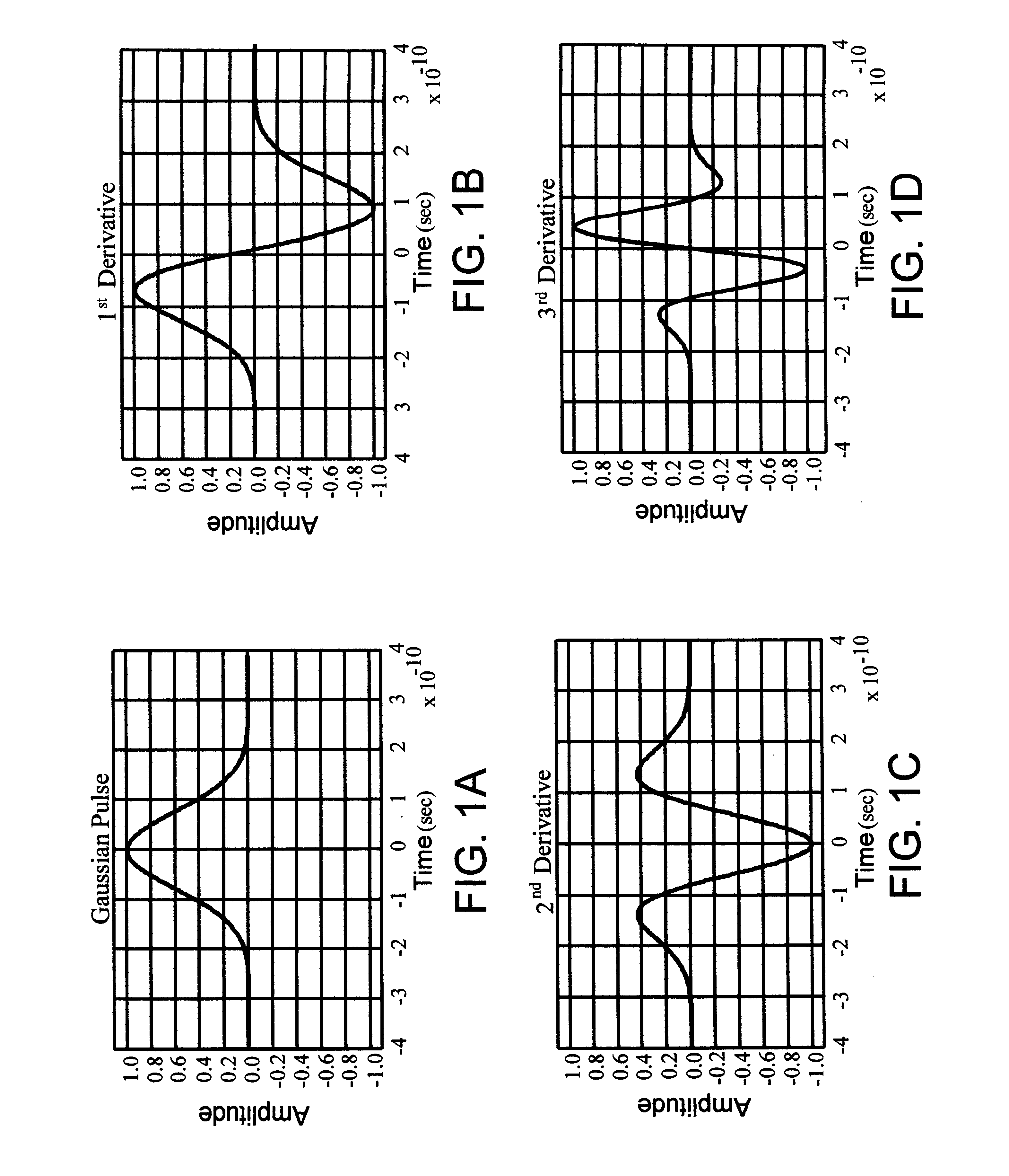
Referring to FIG. 14, there is a diagram illustrating the intrusion detection system 1100 in accordance with the present invention. The intrusion detection system 1100 includes a transmitting impulse radio unit 1000 (described above as the UWB transmitter 1000) and a receiving impulse radio unit 900 (described above as the UWB scanning receiver 900). The transmitting impulse radio unit 1000 transmits an impulse radio signal 1402 having a known pseudorandom sequence of pulses that look like a series of Gaussian waveforms (see FIG. 1).

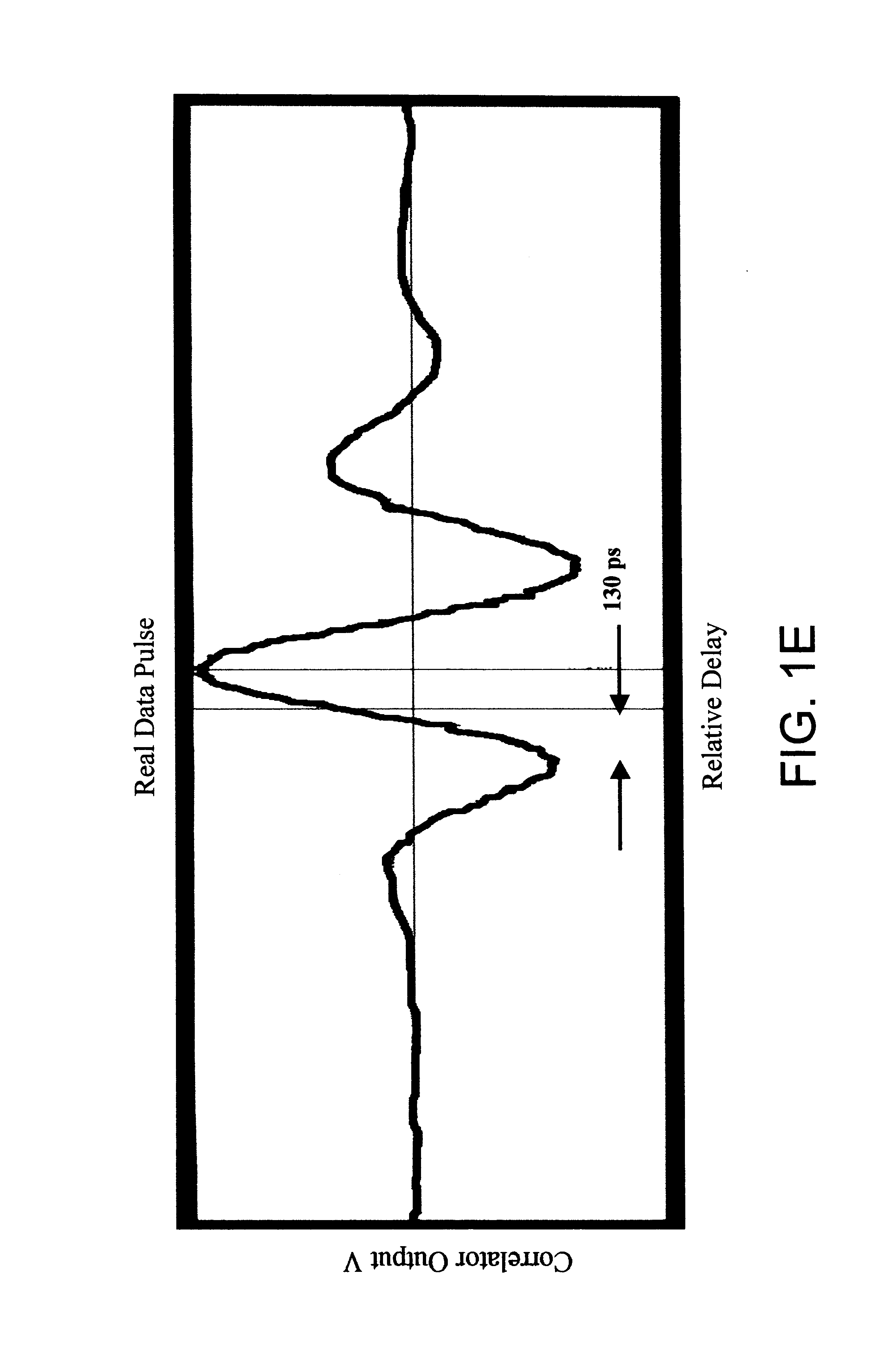
Initially, the impulse radio signal 1402 is transmitted within and through a protection zone 1104 that does not have an intruder 1102. The receiving impulse radio unit 900 receives the impulse radio signal 1402 and generates a first waveform 1502 (an exemplary first waveform is shown in FIG. 15a). The first waveform 1502 is a time domain representation of the actual distortion of the transmitted Gaussian waveform after being filtered by the environment a...

second embodiment

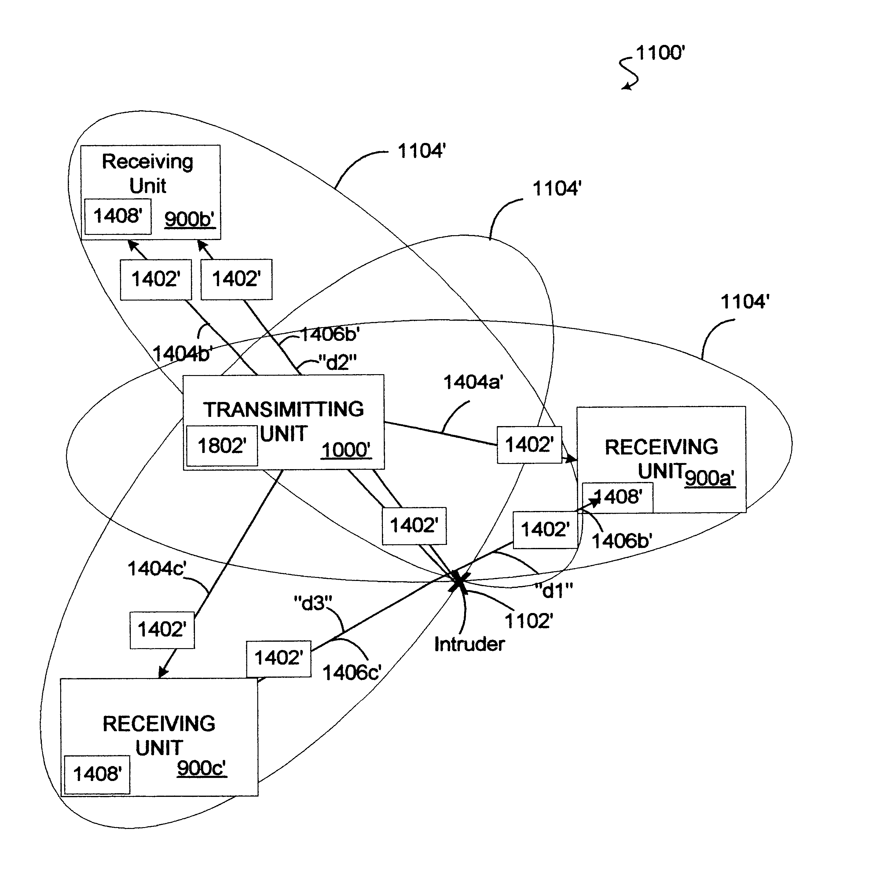
At step 1610, if the intruder 1102 is determined to be in the protection zone 1104, the processor 1408 could then calculate the difference "d" between the direct path between the transmitter 1000 and receiver 900 and the indirect path 1402 by knowing the elapsed time "t" between the initial wavefront 1506 and the multipath reflection part 1508 of the second waveform 1504 (see FIG. 15b). For instance, the distance "d" can be calculated to be 0.984 feet for each nanosecond in the elapsed time "t" between the initial wavefront 1506 and the multipath reflection part 1508 of the second waveform 1504 (see FIG. 15b). In this embodiment, the intruder 1102 could be in one of many places indicated by the ellipse shown in FIG. 14 (shown are two possible positions of the intruder 1102). Reference is made to the intrusion detection system 1100' which can determine the real location of the intruder 1102.

At step 1612, the receiving impulse radio unit 900 sounds an alarm and / or informs remote secur...

third embodiment

Again it should be understood that there may be many items (e.g., walls, trees, furniture . . . ) within the protection zone 1104' that could cause a multipath reflection part in the first waveform 1502a', 1502b' and 1502c' and the second waveform 1504a', 1504b' and 1504c' but it is the difference between the two waveforms that indicates the presence of one or more intruders 1102'. Moreover, it should be noted that the shape of the protection zone 1104' in this embodiment is basically arbitrary as compared to the specially designed shape of the protection zone 1104" the

After calculating the distances "d1", "d2" and "d3" which are the differences between the direct paths 1402' and indirect paths 1406a', 1406b' and 1406c', each receiving impulse radio unit 900a', 900b' and 900c' and transmitting unit 1000' forwards their calculated distance "d1", "d2" or "d3" to the transmitting impulse radio unit 1000'. Thereafter, the transmitting impulse radio unit 1000' has a processor 1802' that ...


PUM


Abstract

An intrusion detection system and method are provided that can utilize impulse radio technology to detect when an intruder has entered a protection zone. In addition, the intrusion detection system and method can utilize impulse radio technology to determine a location of the intruder within the protection zone and also track the movement of the intruder within the protection zone. Moreover, the intrusion detection system and method can utilize impulse radio technology to create a specially shaped protection zone before trying to detect when and where the intruder has penetrated and moved within the protection zone.

Description

1.Field of the InventionThe present invention relates in general to the security field and, in particular, to a system and method capable of using impulse radio technology to detect when an intruder has entered a protection zone and where in the protection zone the intruder is currently located.2. Description of Related ArtToday there are many types of intrusion detection systems that can detect and signal an alarm if a person enters a protection zone. One type of an intrusion detection system uses sensors to detect an intruder where the sensors are placed on the doors, windows or any opening of a building that can be breached by the intruder. Thus, if an intruder opens a door or window a circuit in a sensor is interrupted and then the intrusion detection system sounds an alarm and / or alerts remote security personnel. This type of intrusion detection system can be employed only where a building or structure is available to support the wiring for the sensors.Another type of intrusion...

Claims


Application Information

Patent Timeline
Patent Type & Authority Patents(United States)
IPC IPC(8): G01S13/02G01S13/04G01S13/00G01S13/42G01S7/28G01S7/282G01S7/285G01S7/292G01S13/87
CPCG01S7/282G01S7/285G01S7/292G01S13/0209G01S13/04G01S13/42G08B13/187G01S13/003G01S13/878H04B2001/6908
Inventor HALL, DAVID J.YANO, SCOTT M.SCHANTZ, HANS G.
Owner HUMATICS CORP
Why Eureka
Try Eureka