Adjustable inclined angle structure for computers

Inactive Publication Date: 2003-11-11
MITAC TECH CORP
View PDF15 Cites 77 Cited by
  • Summary
  • Abstract
  • Description
  • Claims
  • Application Information

AI Technical Summary

Benefits of technology

The main object of the present invention is to provide a structure for adjusting the incline angle of a computer. It not only provides users with different viewing angles,

Problems solved by technology

However, because different users have different desired viewing angles, such a design cannot satisfy every user's needs.
So, t

Method used


Image

  • Adjustable inclined angle structure for computers
  • Adjustable inclined angle structure for computers
  • Adjustable inclined angle structure for computers

Examples


Embodiment Construction

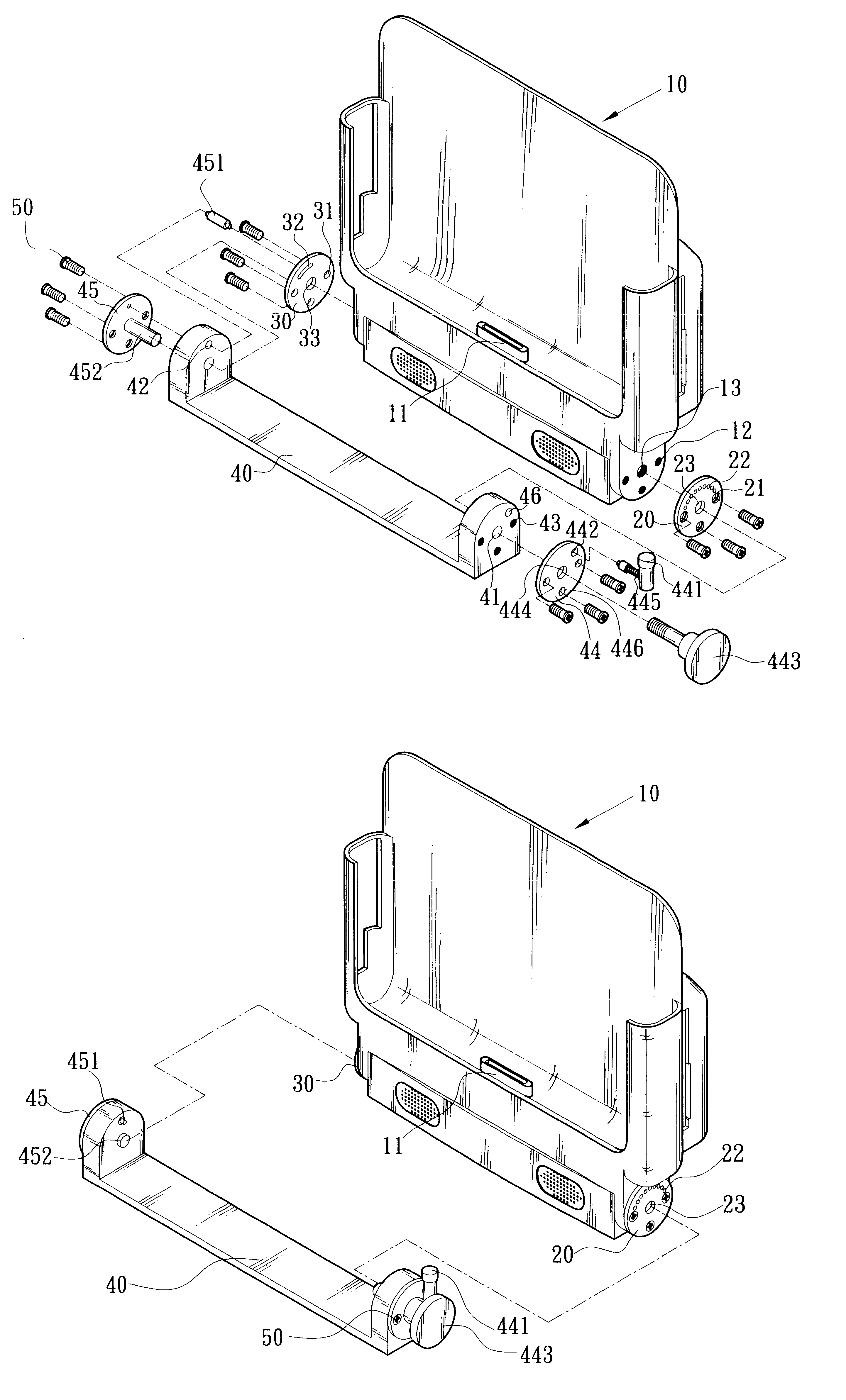
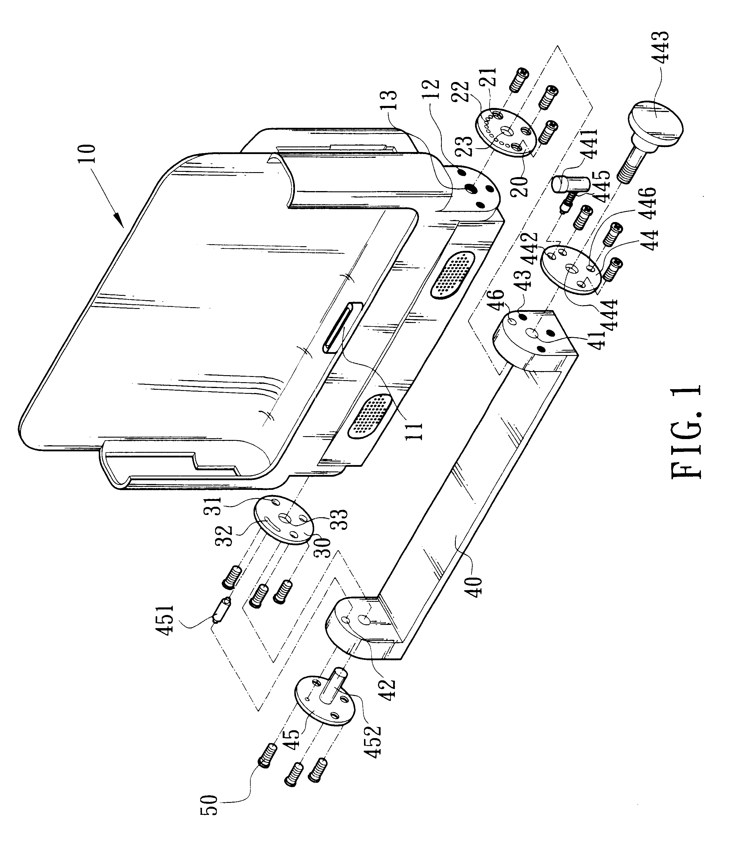
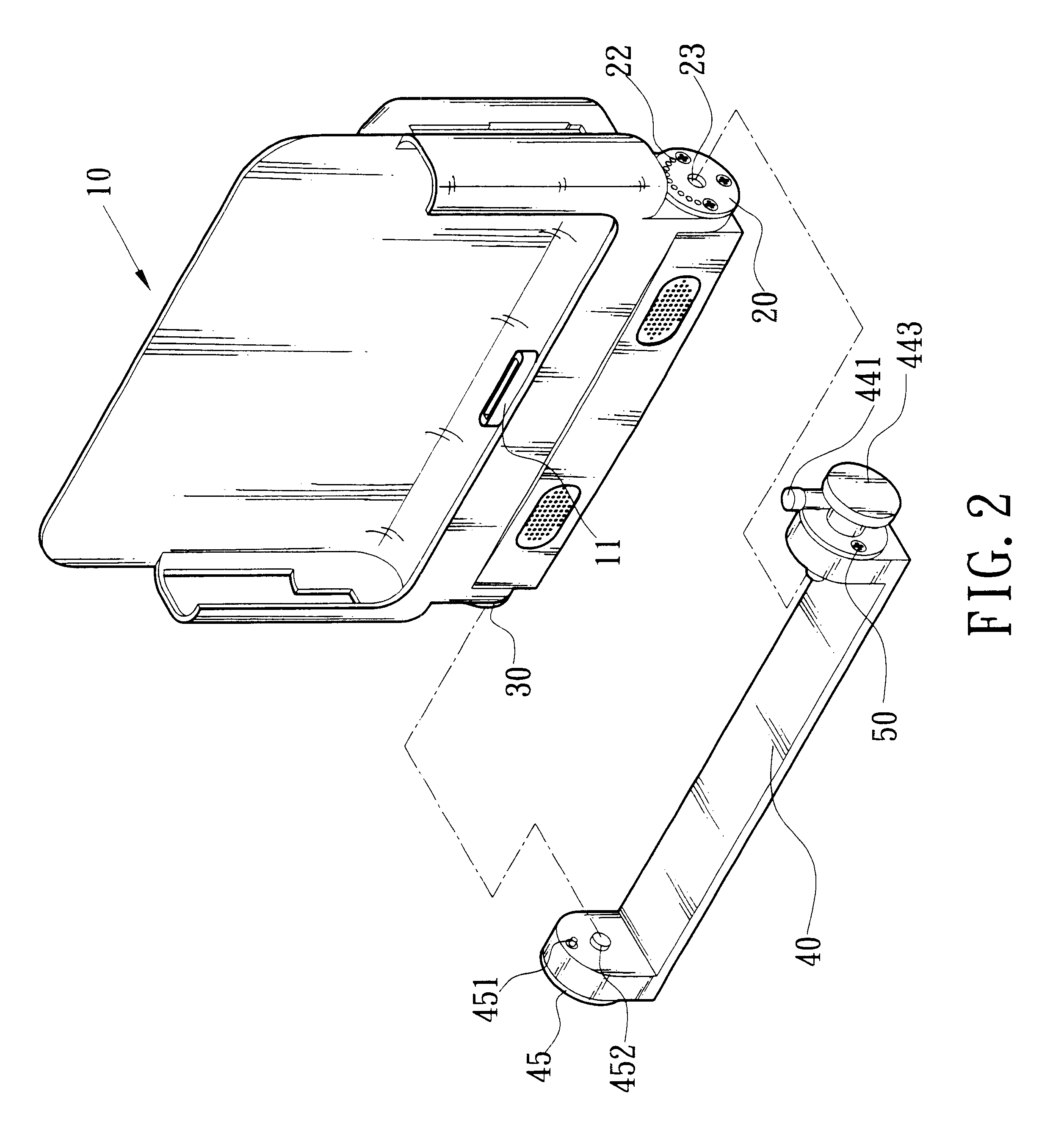
The adjustable incline angle structure disclosed by the present invention is mainly for use with industrial computers that can be separated from the present invention. The present invention can provide different incline angles when it is located on a platform, enabling users to view pictures displayed on the screen from all different directions.

As shown in FIGS. 1, 2 and 3, the present invention is mainly included of a receiver element 10, a pair of rotating disks and a base 40. The disks consist of a first rotating disk 20 and second rotating disk 30.

A front plate, rear plate, and bottom plate connecting two side plates compose the receiver element, so as to form a receiving space for the industrial computer. A plug 11 is disposed at the proper position on the inner side of the bottom plate so as to let the jack (not shown in the figures) of the industrial computer connect with the plug 11 when the industrial computer is positioned in the receiving space of the receiver element 10....


PUM


Abstract

An adjustable inclined angle structure of a computer. It mainly uses a pair of rotating disks to adjust and fix the inclined angle of a computer when it is installed. One of rotating disks use a handlebar with spring pin to buckle up with dividing holes of the rotating disk to fix the inclined angle. Another rotating disk has a long hole corresponding to an anchor element to limit a starting point and an end point of inclined angle travel caused by the above-mentioned dividing holes so that it can be used to adjust the inclined angle of computer, and avoid falling down due to an over-adjustment.

Description

The present invention relates to a structure for adjusting the incline angle of a computer, applied to industrial computers that can be separated from a base, and more particularly to a structure that can adjust an inclined angle of an industrial computer.TECHNICAL BACKGROUNDGenerally speaking, most industrial computers are designed to be portable so as to provide convenience for users. On the other hand, when the computer must be used on a table or platform, we must use a mechanism to stand it up so as to allow the user to see the screen. So that users can have a better viewing angle, a structure that can incline to a particular angle is designed and later attached to the above-mentioned structure. However, because different users have different desired viewing angles, such a design cannot satisfy every user's needs. In addition, a user needs not only to assume a standing posture to view the computer screen, but also to adopt other postures to change the viewing angle to view the s...

Claims


Application Information

Patent Timeline
IPC IPC(8): F16C11/10F16C11/04F16M11/02F16M11/10G06F1/16
CPCF16C11/10F16M11/041F16M11/10G06F1/1632Y10T403/32336Y10S248/923F16M2200/024
Inventor TAI, KUANG-CHENG
Owner MITAC TECH CORP
Why Eureka
Try Eureka