AI technical title is built by PatSnap AI team. It summarizes the technical point description of the patent document.
a technology of heated glass and molds, applied in glass rolling equipment, glass tempering equipment, manufacturing tools, etc., can solve the problem of more difficult to change molds between different production runs, and cannot utilize the same molds
Inactive Publication Date: 2004-04-13
GLASSTECH
View PDF32 Cites 40 Cited by
Summary
Abstract
Description
Claims
Application Information
AI Technical Summary
This helps you quickly interpret patents by identifying the three key elements:
Problems solved by technology
Method used
Benefits of technology
Problems solved by technology
The heated environment also makes it more difficult to change molds between different production runs that cannot utilize the same molds.
Method used
Image
Click on the blue label to locate the original text in one second.
Reading with bidirectional positioning of images and text.
Examples
Embodiment Construction
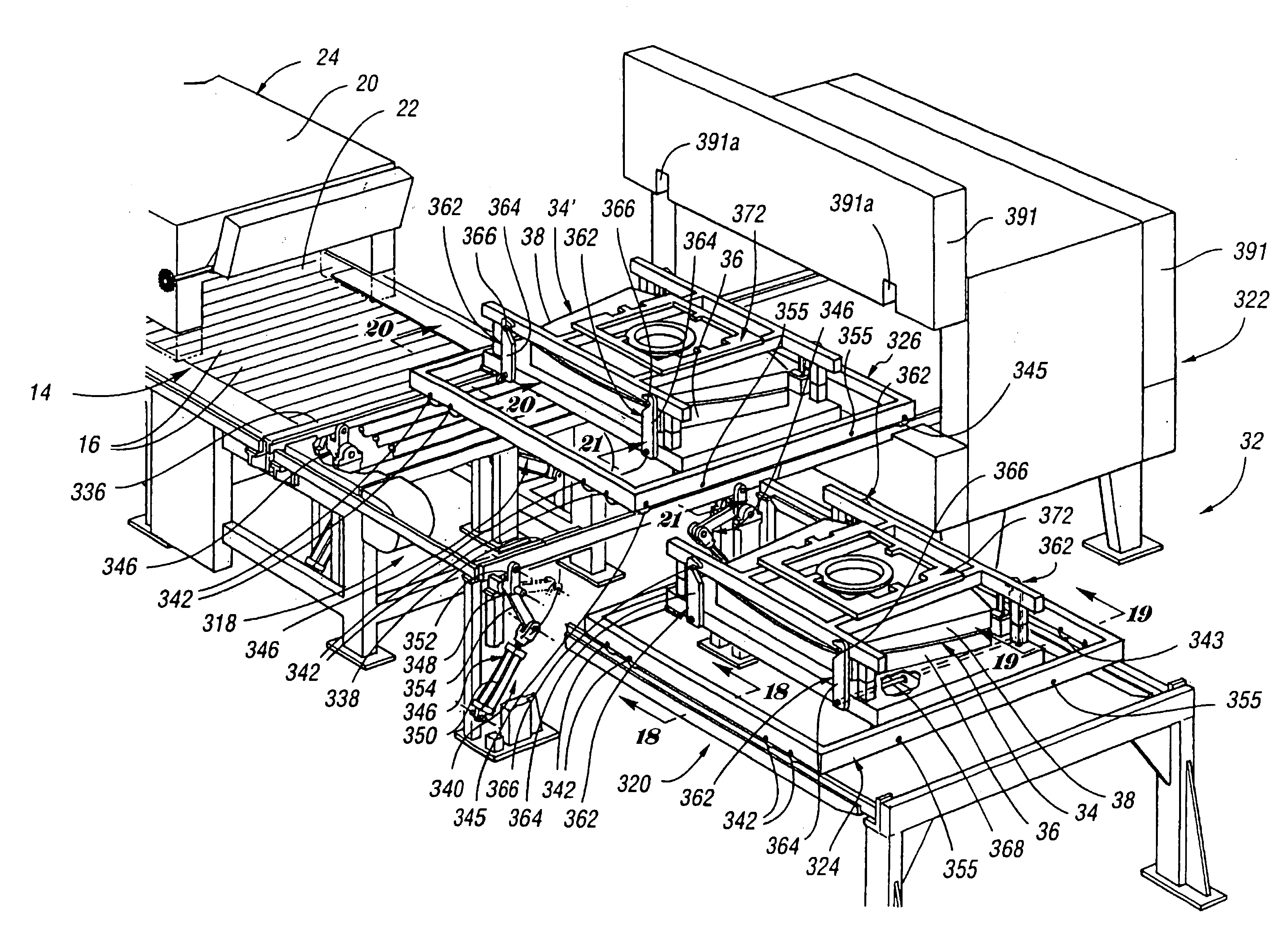
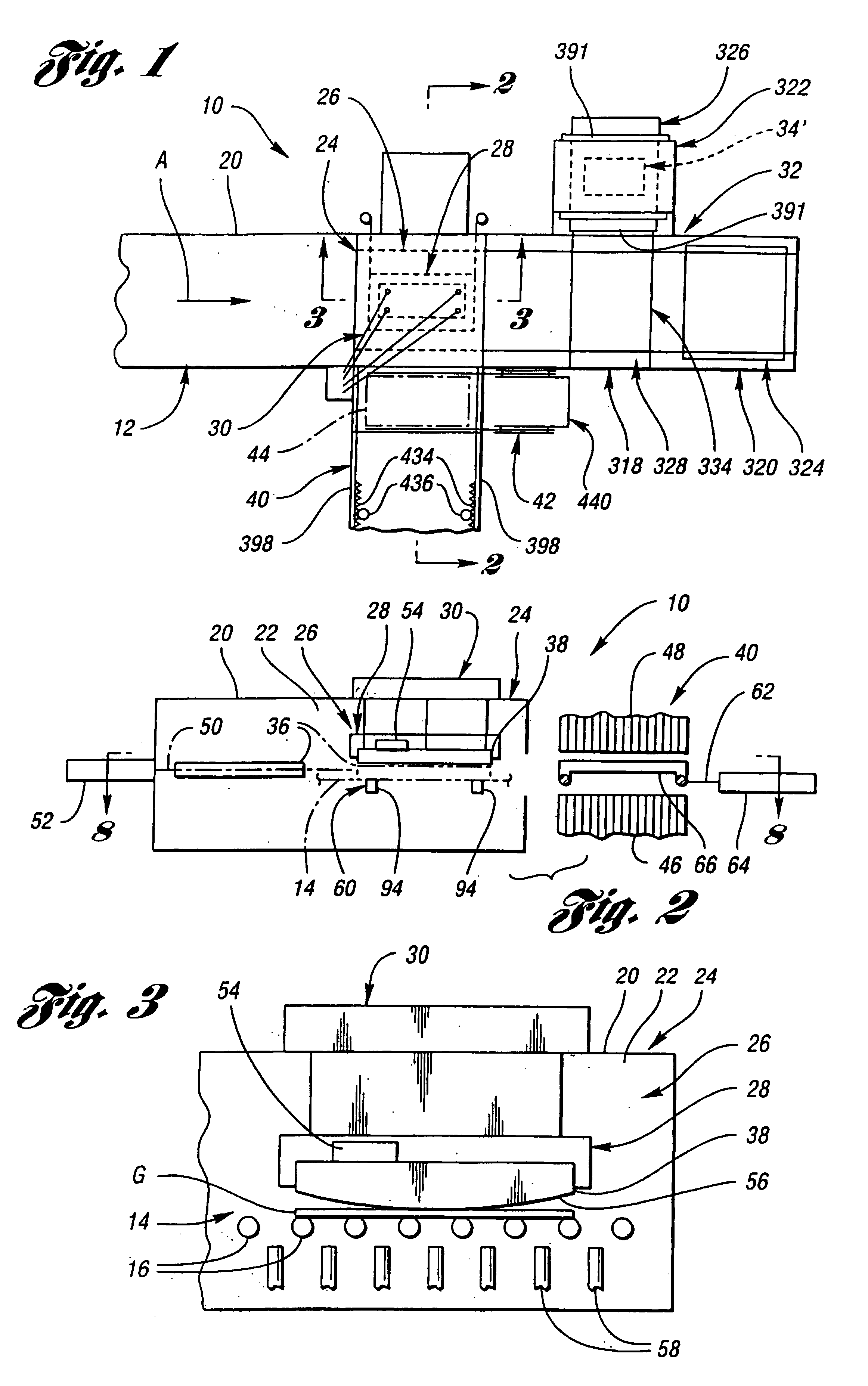
With reference to FIG. 1 of the drawings, a glass sheet forming and quench system embodying the invention is generally indicated by 10 and will be summarily described before a detailed description of each station, apparatus, and method of operation utilized to perform the forming and quenching of glass sheets. System 10 includes an elongated furnace 12 in which glass sheets are heated during movement along a primary system axis A, which movement is also referred to as a direction of conveyance through the system. The conveyance within the furnace 12 may be on a roll conveyor 14 that includes rolls 16 as illustrated in FIGS. 2-7. As specifically shown in FIG. 7, the glass sheets are introduced into the system 10 at a loading table 18 for movement into a system housing 20 that defines a heated chamber 22 as shown in FIGS. 2-6.
With continuing reference to FIG. 1, the glass sheets after heating to forming temperature are moved to the right to a forming station 24 that includes apparatus...
PUM
Property
Measurement
Unit
temperature
aaaaa
aaaaa
time
aaaaa
aaaaa
vertical movement
aaaaa
aaaaa
Abstract
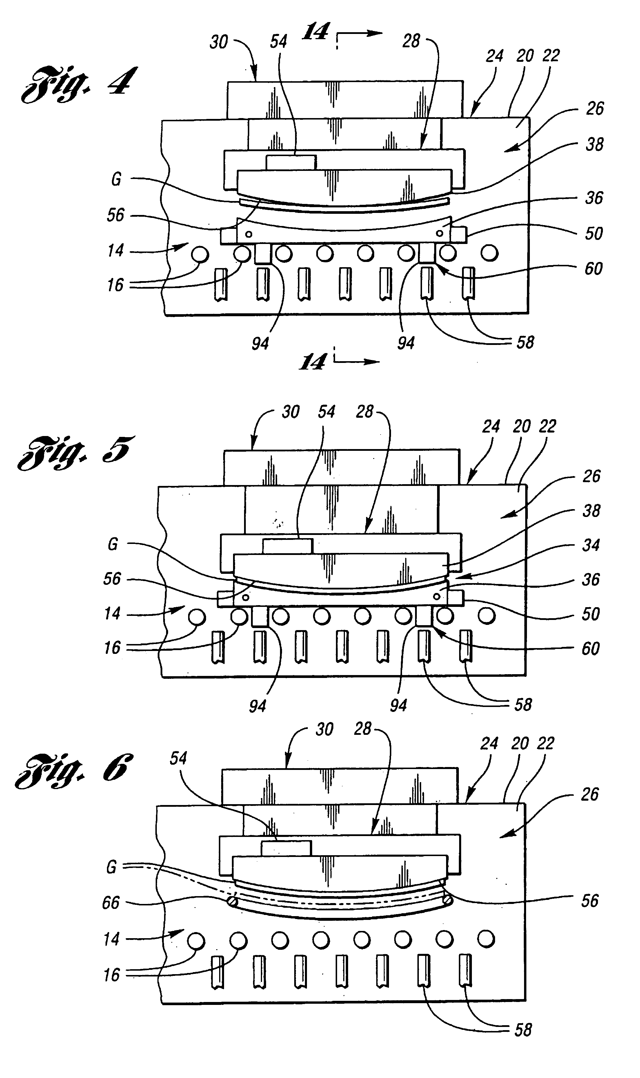
Apparatus (26) and a method for forming heated glass sheets in a heated chamber (22) of a housing (20) includes an upper mold support assembly (28) for supporting an upper mold (38) within the heated chamber for cyclical vertical movement between upper and lower positions. A lower mold shuttle (50) supports a lower mold (36) for movement between an idle position horizontally spaced from the upper mold and a use position below the lower mold. The apparatus also includes a lower mold support assembly (60) to which the lower mold is transferred from the lower mold shuttle (50) to provide support thereof while permitting horizontal alignment with the upper mold upon each cycle of downward movement to form a heated glass sheet between the molds. The lower mold shuttle (50) is supported by vertically movable rollers (70) to provide the transfer between the lower mold shuttle and the lower mold support assembly (60). A quench station (40) includes a quench shuttle (62) that moves a quench ring (66) to receive the formed glass sheet from the upper mold (38) and to then move the formed glass sheet between lower and upper quench modules (46,48) of the quench station for quenching.
Description
This invention relates to apparatus and a method for forming heated glass sheets while providing alignment between lower and upper molds used in the forming.Glass sheets are conventionally formed by heating within a furnace and then forming within a heated chamber prior to delivery for cooling. Such cooling can be slow cooling to provide annealing or faster cooling that provides heat strengthening or tempering. In connection with heating of the glass sheets, see U.S. Pat. Nos. 3,806,312 McMaster et al.; 3,947,242 McMaster et al.; 3,994,711 McMaster; 4,404,011 McMaster; and 4,512,460 McMaster. In connection with glass sheet forming, see U.S. Pat. Nos. 4,282,026 McMaster et al.; 4,437,871 McMaster et al.; 4,575,390 McMaster; U.S. Pat. No. 4,661,141 Nitschke et al.; U.S. Pat. No. 5,004,491 McMaster et al.; and U.S. Pat. No. 5,472,470 Kormanyos et al. In connection with the cooling, see U.S. Pat. Nos. 3,936,291 McMaster; 4,470,838 McMaster et al.; 4,525,193 McMaster et al.; U.S. Pat. No...
Claims
Application Information
Patent Timeline
Application Date:The date an application was filed.
Publication Date:The date a patent or application was officially published.
First Publication Date:The earliest publication date of a patent with the same application number.
Issue Date:Publication date of the patent grant document.
PCT Entry Date:The Entry date of PCT National Phase.
Estimated Expiry Date:The statutory expiry date of a patent right according to the Patent Law, and it is the longest term of protection that the patent right can achieve without the termination of the patent right due to other reasons(Term extension factor has been taken into account ).
Invalid Date:Actual expiry date is based on effective date or publication date of legal transaction data of invalid patent.

