
Systems and methods providing bi-directional passage of an object via an articulated member

a technology of articulated members and objects, applied in the field of systems and methods providing bi-directional passage of objects, can solve problems such as degraded system performance, affecting image quality, and affecting system performan

Inactive Publication Date: 2004-08-31
XEROX CORP
View PDF9 Cites 28 Cited by
  • Summary
  • Abstract
  • Description
  • Claims
  • Application Information

AI Technical Summary

Benefits of technology

The invention provides an articulated knee joint flag that allows media to pass through processing paths without damaging the flag or the object. The flag can be used in sheet media handling devices to improve system performance and image quality. The flag has a pivotable body and foot that can indicate the position of an object without interfering with its movement. The flag can also be used to remove media that is jammed in the processing path. The invention also provides an articulated knee joint flag with a pivotable flag body and foot that can indicate the position of an object without interfering with its movement. The flag can be used in a processing path of a copier or printer to improve system performance and image quality.

Problems solved by technology

The sensor flags used in conventional sheet media handling devices may degrade system performance in several ways.
The system performance may be degraded, for example by tearing the sheet of media, by breaking flags when attempting to remove a sheet of media from a processing path, by impairing image quality by reducing the uniform application of heat and / or pressure to the sheets of media, or by increasing the risk of interfering with other existing components of the sheet media handling device.
In such media handling devices, the increased slot size may either reduce the uniformity of heat and pressure distribution to a sheet of media as it travels in a processing path or provide a catch point for a sheet edge.

Method used


Image

  • Systems and methods providing bi-directional passage of an object via an articulated member
  • Systems and methods providing bi-directional passage of an object via an articulated member
  • Systems and methods providing bi-directional passage of an object via an articulated member

Examples


Embodiment Construction

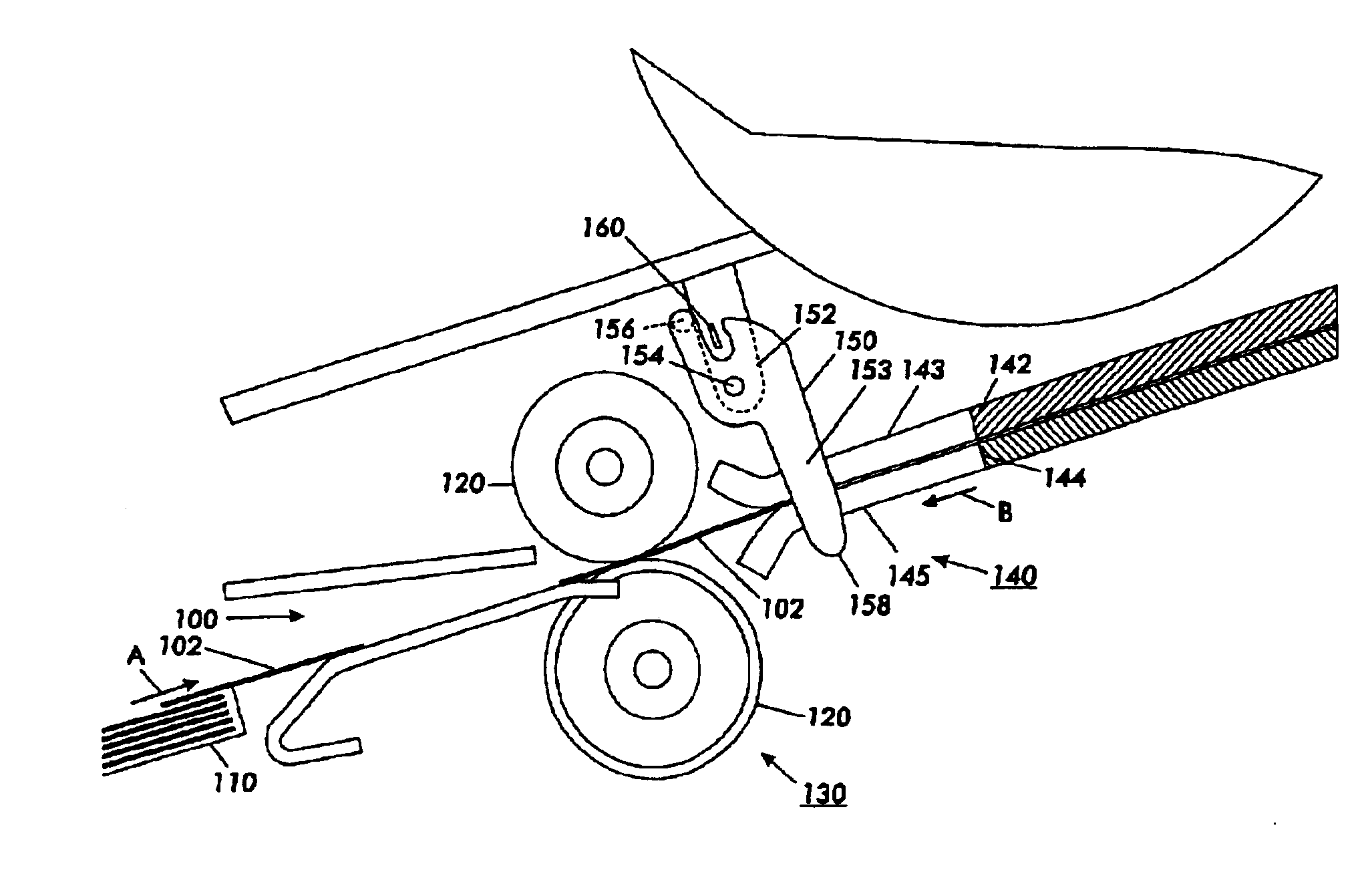
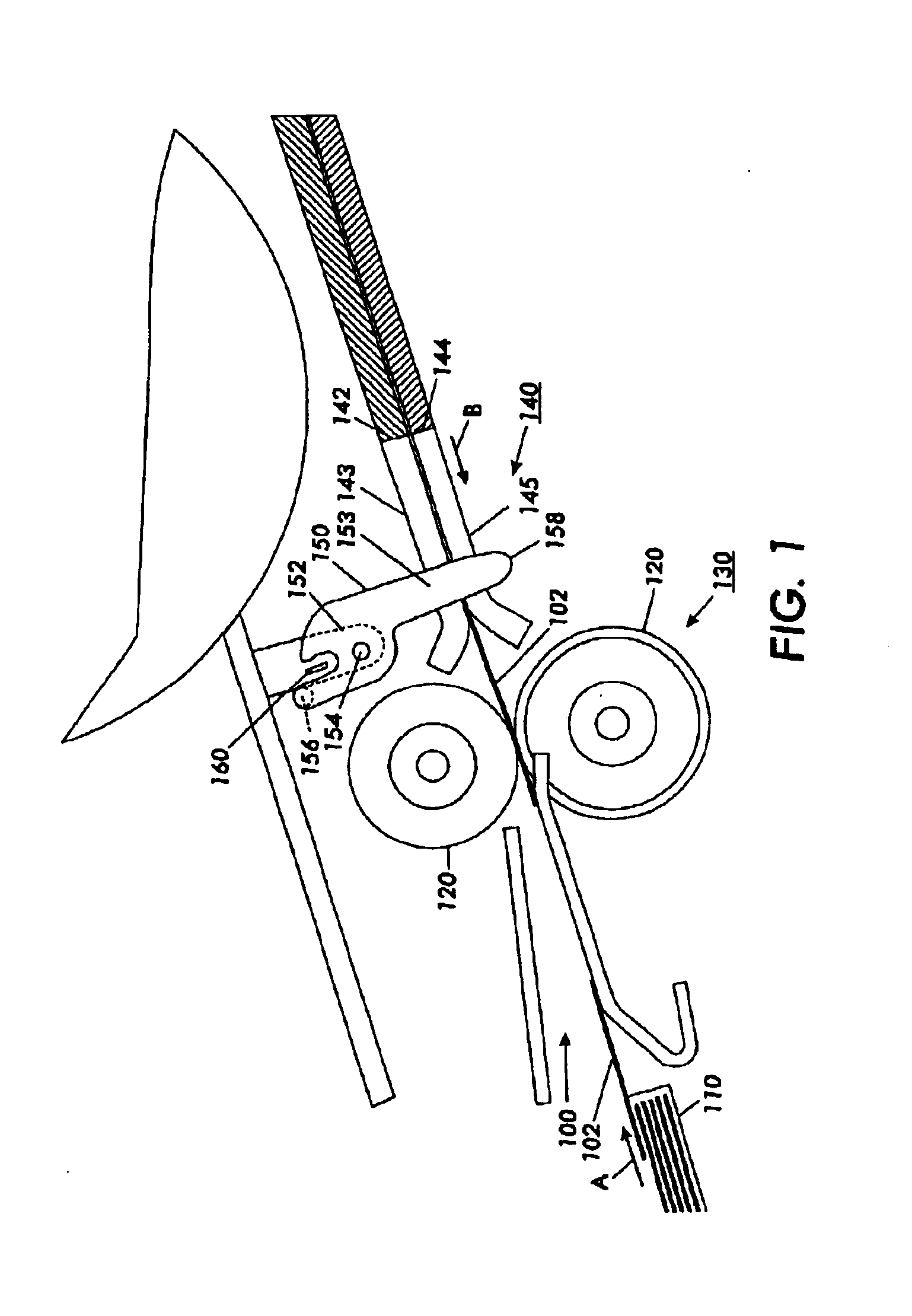
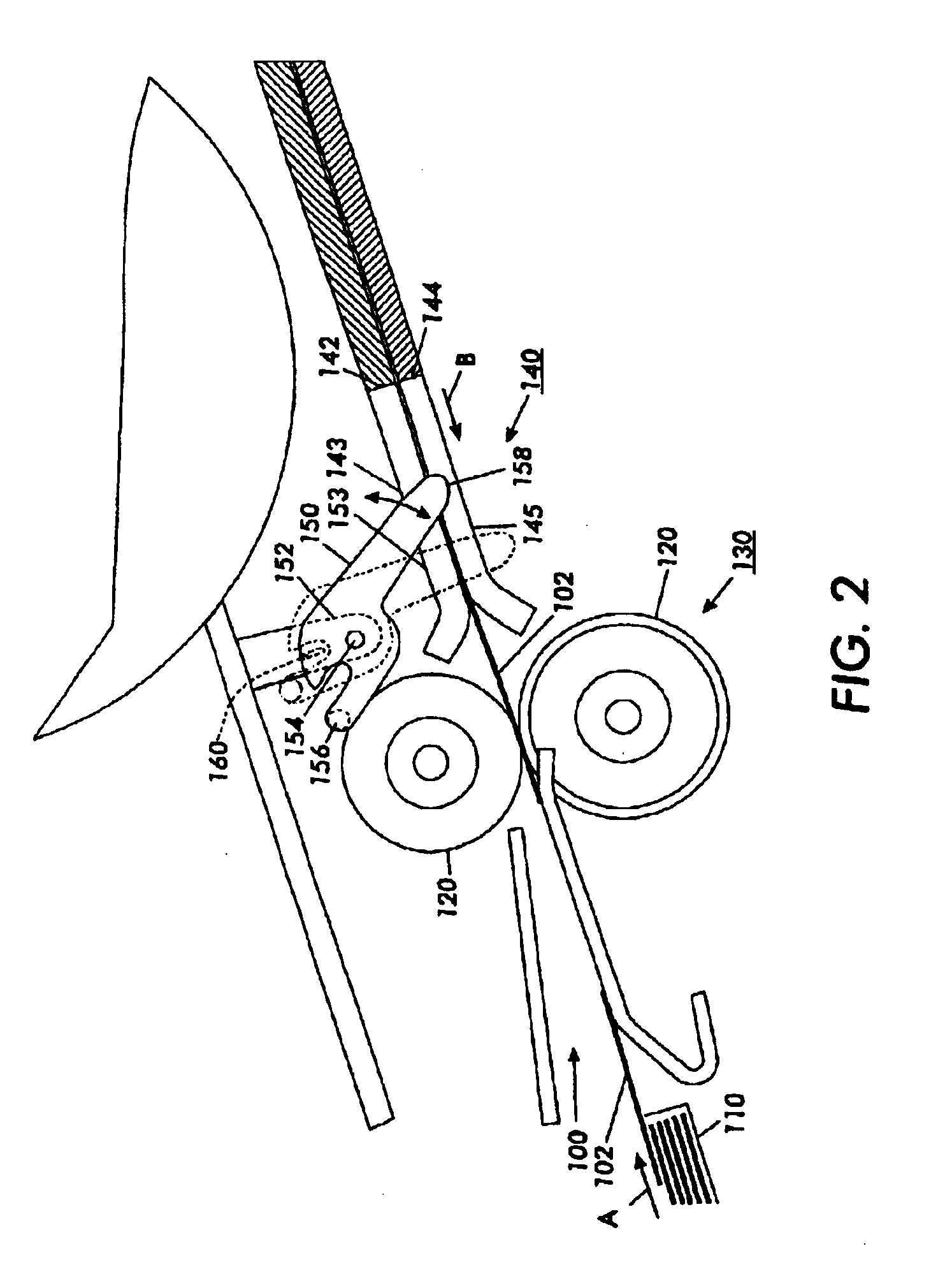
Conventional copying / scanning and / or printing devices provide a processing path 100 through which media travels to produce a final copied and / or printed product. FIGS. 1-3 show, for example, a typical copier and / or printer, in which a sheet of media 102 is provided from a paper tray 110 to a processing path 100 having an intended processing path 100 direction A. The sheet of media 102 is urged along the processing path 100 by driving rollers 120 that move the sheet of media 102 to a media heating stage 140. In the media heating stage 140, the sheet of media 102 travels through a pair of guiding plates to prepare the sheet of media 102 to evenly accept the image at the following stage. The sheet of media 102 then proceeds to subsequent processing stages or exits the copier and / or printer as a final product.

As the sheet of media 102 travels along the processing path 100 by the urging of the driving rollers 120, for example, a single leg flag 150 may be used to identify a position or l...


PUM


Abstract

An articulated flag body member permitting bi-directional passage of an object. The articulated flag body member has a flag body pivotably connected to a flag foot. As rotation of the flag foot occurs in one direction, the flag body rotates by engagement of a recess of the flag foot with a stop member extending along a projecting leg of the flag body. As the flag body rotates, a notch at the upper portion of the flag body changes positions such that light, or other signals, may no longer pass through the notch. Thus, positional indication of an object detected by rotation of the flag body. As rotation of the flag foot occurs in an opposite direction, an object may be extricated or removed.

Description

1. Field of InventionThis invention relates to systems and methods providing bi-directional passage of an object in a processing path by using an articulated member.2. Description of Related ArtThe sensor flags used in conventional sheet media handling devices may degrade system performance in several ways. The system performance may be degraded, for example by tearing the sheet of media, by breaking flags when attempting to remove a sheet of media from a processing path, by impairing image quality by reducing the uniform application of heat and / or pressure to the sheets of media, or by increasing the risk of interfering with other existing components of the sheet media handling device. Further, conventional designs commonly comprise unitary, single piece flags that require an increased slot size in the associated structures of the sheet media handling device, such as the pressure plate and / or heating plates of conventional copying, printing or document scanning devices. In such med...

Claims


Application Information

Patent Timeline
Patent Type & Authority Patents(United States)
IPC IPC(8): B65H7/02
CPCB65H7/02B65H2511/20B65H2513/40B65H2513/41B65H2553/612B65H2220/01B65H2220/08B65H2220/03Y10S271/902B65H2553/61
Inventor CHAMBERS, RICHARD G.ROBILLARD, CRAIG F.MANNIE, BARRY G.MACLANE, DONALD B.
Owner XEROX CORP
Learn More