
Orthopedic stabilization device and method

a stabilizing device and orthopedic technology, applied in the field of orthopedic stabilization structure, can solve the problems of common frailties, inability to orient the stabilizing structure, and the current orthopedic procedure involving the stabilization of the skeletal structur

Inactive Publication Date: 2004-10-05
REED MEDICAL DEVICES
View PDF17 Cites 56 Cited by
  • Summary
  • Abstract
  • Description
  • Claims
  • Application Information

AI Technical Summary

Problems solved by technology

Orthopedic procedures involving stabilization of skeletal structure presently suffer from two common frailties: the first is the inability to orient the stabilizing structure for a multiplicity of common angulations and the second is the failure to provide a reliable thread portion which engages bone of the patient.

Method used


Image

  • Orthopedic stabilization device and method
  • Orthopedic stabilization device and method
  • Orthopedic stabilization device and method

Examples


Embodiment Construction

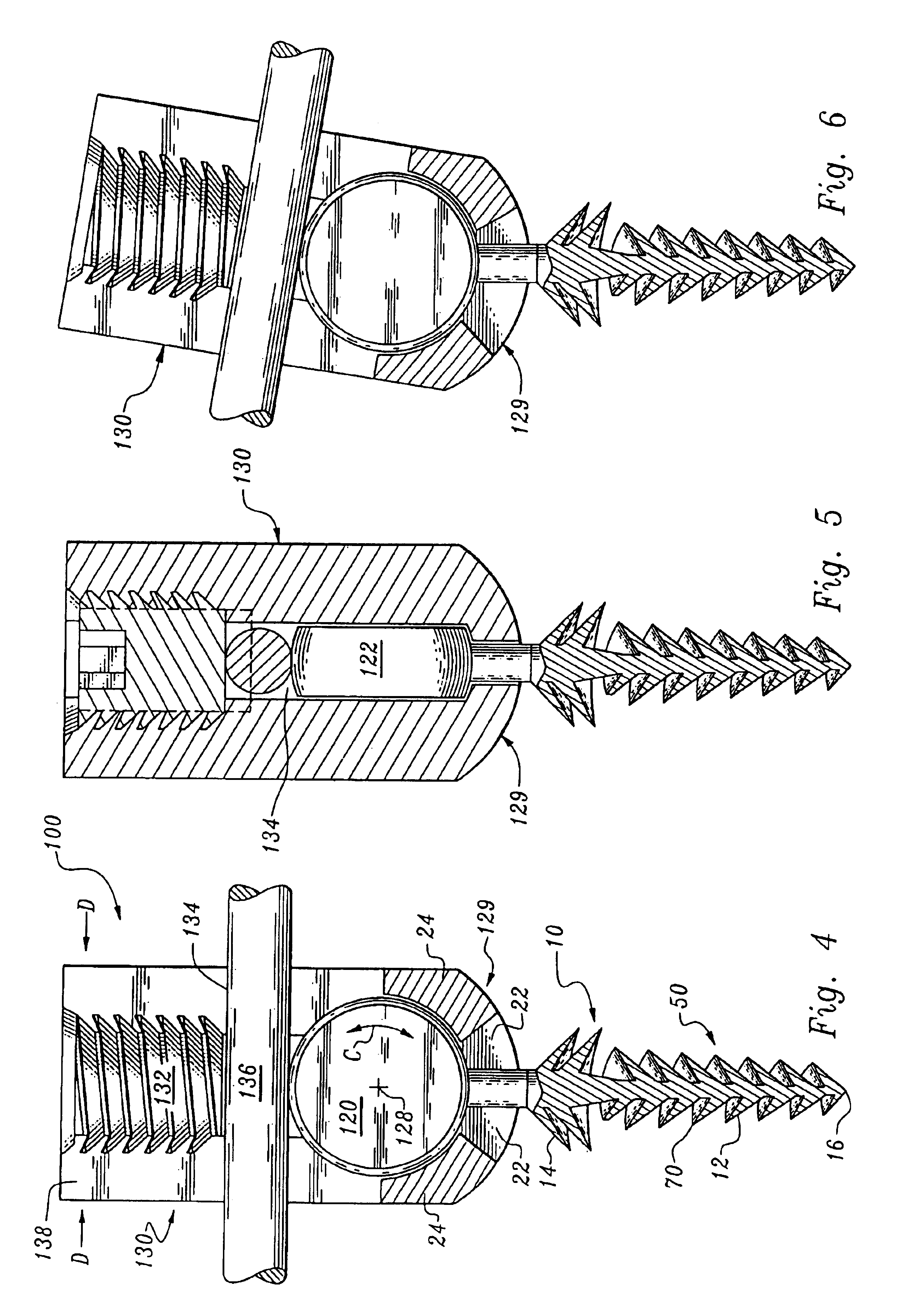
Considering the drawings, wherein like reference numerals denote like parts throughout the various drawing figures, reference numeral 100 is directed to the orthopedic stabilization device according to the present invention.

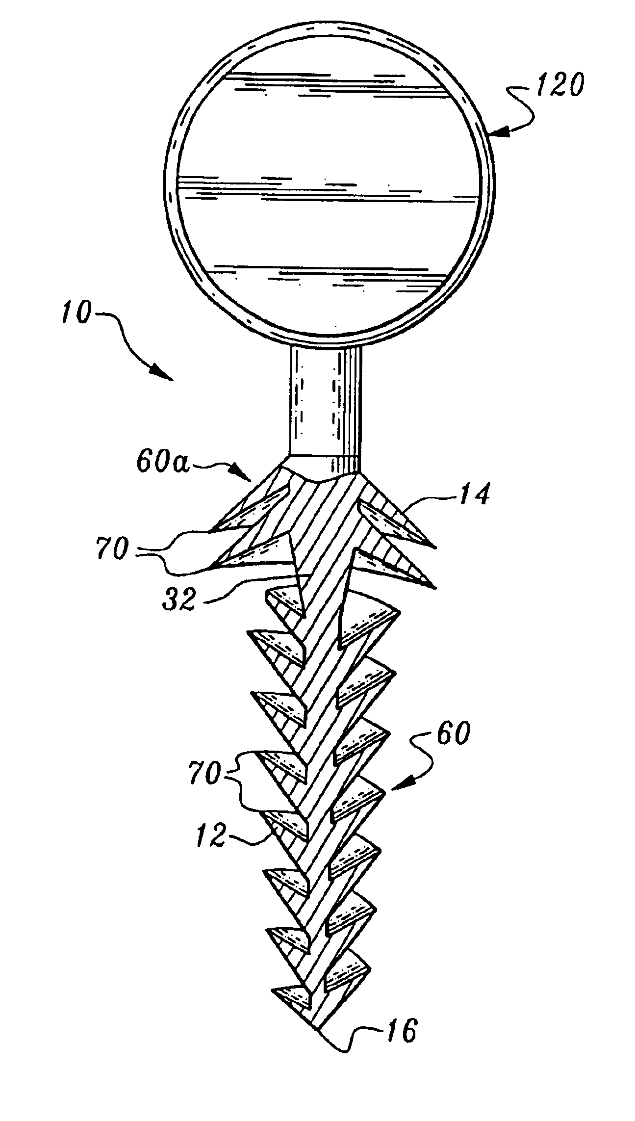
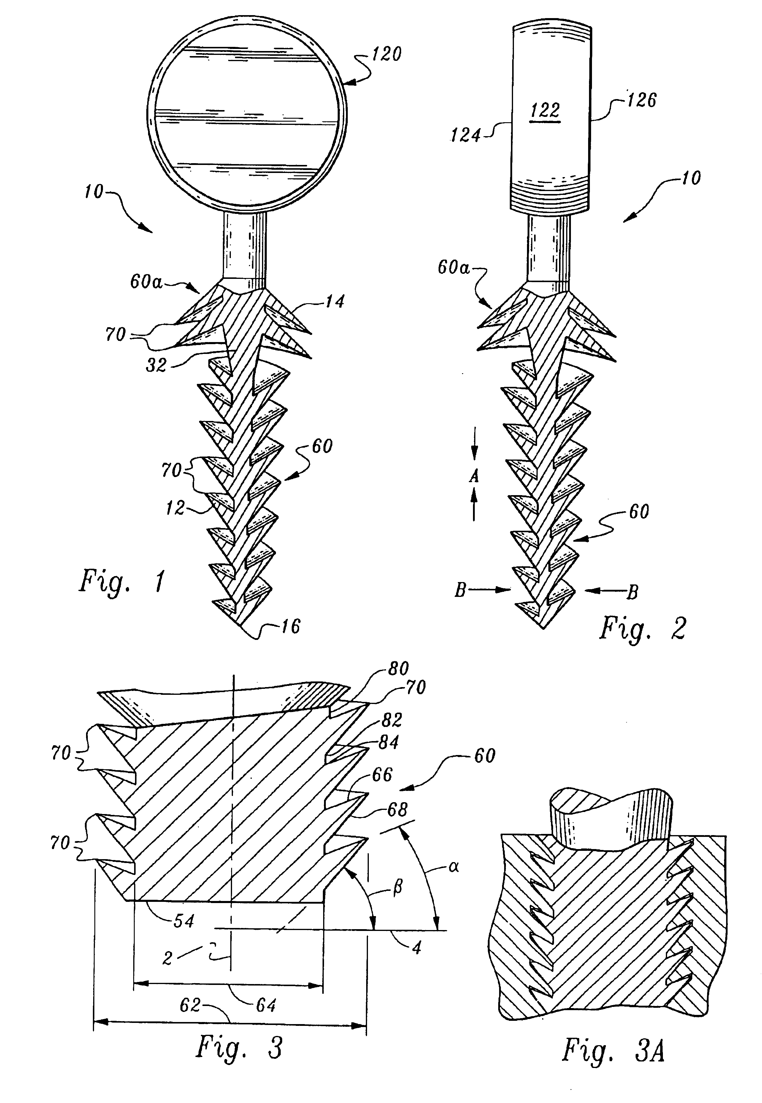
The device 100 allows a threaded fastener 10 to move about the arrow C as shown in FIG. 4 such that although the long axis of the threaded shaft is depicted as presently aligned, it can be rotated and skewed from a vertical long axis of a cup 130 as in FIG. 6. A rotational means 120 embodied as a disc has a cylindrical outer face 122 and planar top and bottom faces 124, 126. Thus, rotation about the arrow C occurs about a geometrical center 128. The disc 120 is integrally fixed to fastener 10. The rotational means 120 is constrained within a cup 130 having a central bore 132, an upper portion of which is provided with threads 111. In addition, a transverse slot 134 is cut along a diameter of the cup which allows slideable insertion therein of both the fastener 10...


PUM


Abstract

An orthopedic stabilization structure including a threaded fastener capable of articulation to accommodate various skeletal geometries, a rod, and a cup supporting the threaded fastener and the rod to be subsequently held in fixed position with respect to the skeletal structure.

Description

The instant invention is directed generally to devices used by orthopedic surgeons to stabilize and align skeletal structures. More specifically, the instant invention includes a fastener capable of rotation about an axis within a supporting cup, the cup contoured to receive a rod therein and a means to fix the rod and rotationally oriented fastener in a fixed position.Orthopedic procedures involving stabilization of skeletal structure presently suffer from two common frailties: the first is the inability to orient the stabilizing structure for a multiplicity of common angulations and the second is the failure to provide a reliable thread portion which engages bone of the patient.The instant invention provides the ability to address various skeletal components in a relational way by allowing articulation of the device in a multiplicity of angulations and to fasten to the skeletal structure to provide greater stabilization with an improved thread pattern which provides both axially c...

Claims


Application Information

Patent Timeline
Patent Type & Authority Patents(United States)
IPC IPC(8): A61B17/80A61B17/64A61B17/70A61B17/60A61B17/86A61B17/68
CPCA61B17/6466A61B17/863A61B17/7038A61B17/7041A61B17/7037A61B17/6475A61B17/7032
Inventor REED, GARY JACK
Owner REED MEDICAL DEVICES
Learn More