Electrical energy conserving kiln method and apparatus

Inactive Publication Date: 2004-10-26
CRESS STEVEN B
View PDF9 Cites 5 Cited by
  • Summary
  • Abstract
  • Description
  • Claims
  • Application Information

AI Technical Summary

Benefits of technology

Another object of this invention is to reduce the electri

Problems solved by technology

A major problem in the firing of ceramic articles has been the problem of firing small loads of product in larger kilns.
However, the problem is that a kiln cannot be operated efficiently and properly with less than a full load.
In the past there have been limited attempts to manufacture and use kilns with a removable ring or the like to attempt to cause an effect

Method used


Image

  • Electrical energy conserving kiln method and apparatus
  • Electrical energy conserving kiln method and apparatus
  • Electrical energy conserving kiln method and apparatus

Examples


Example

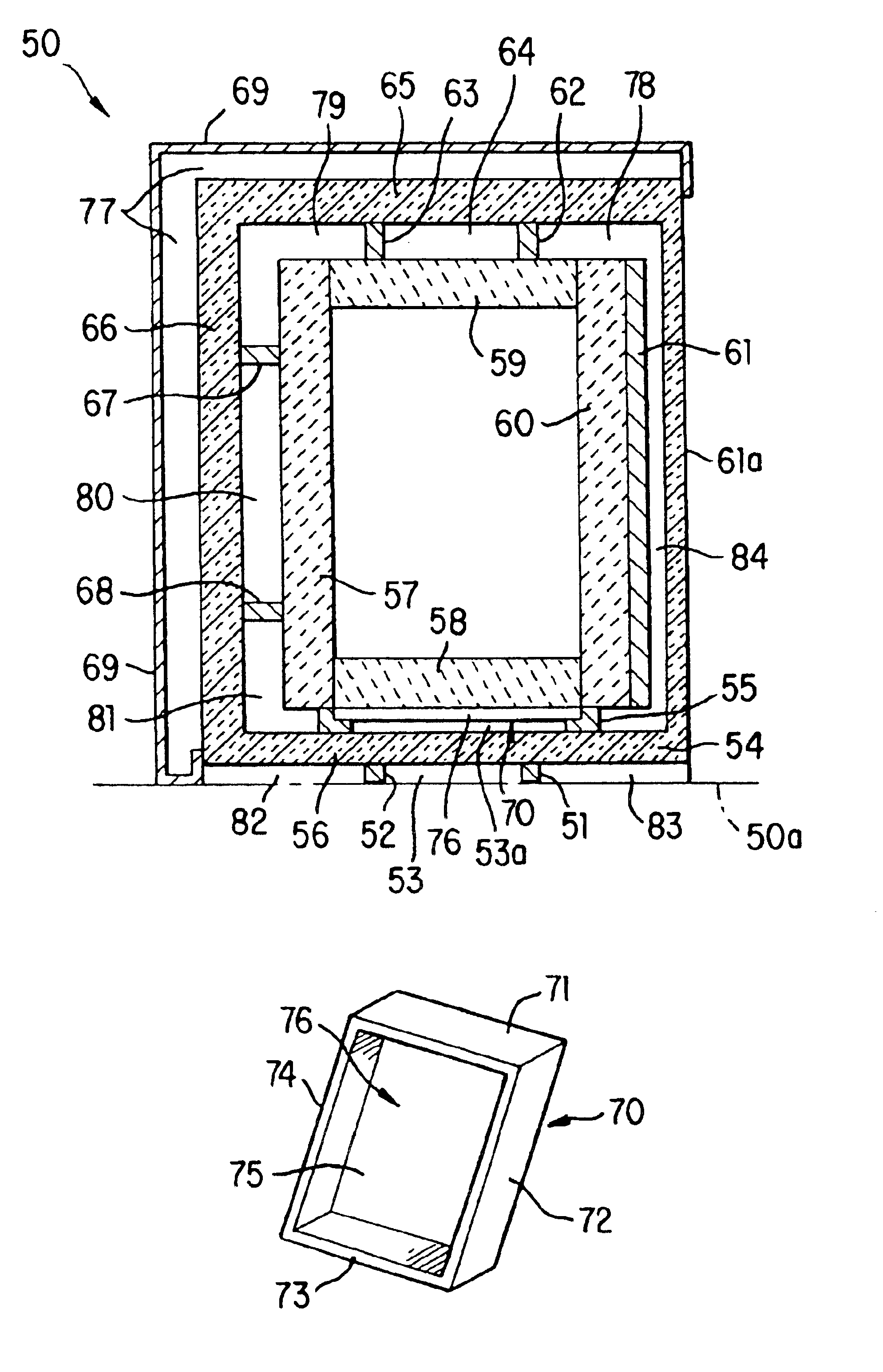
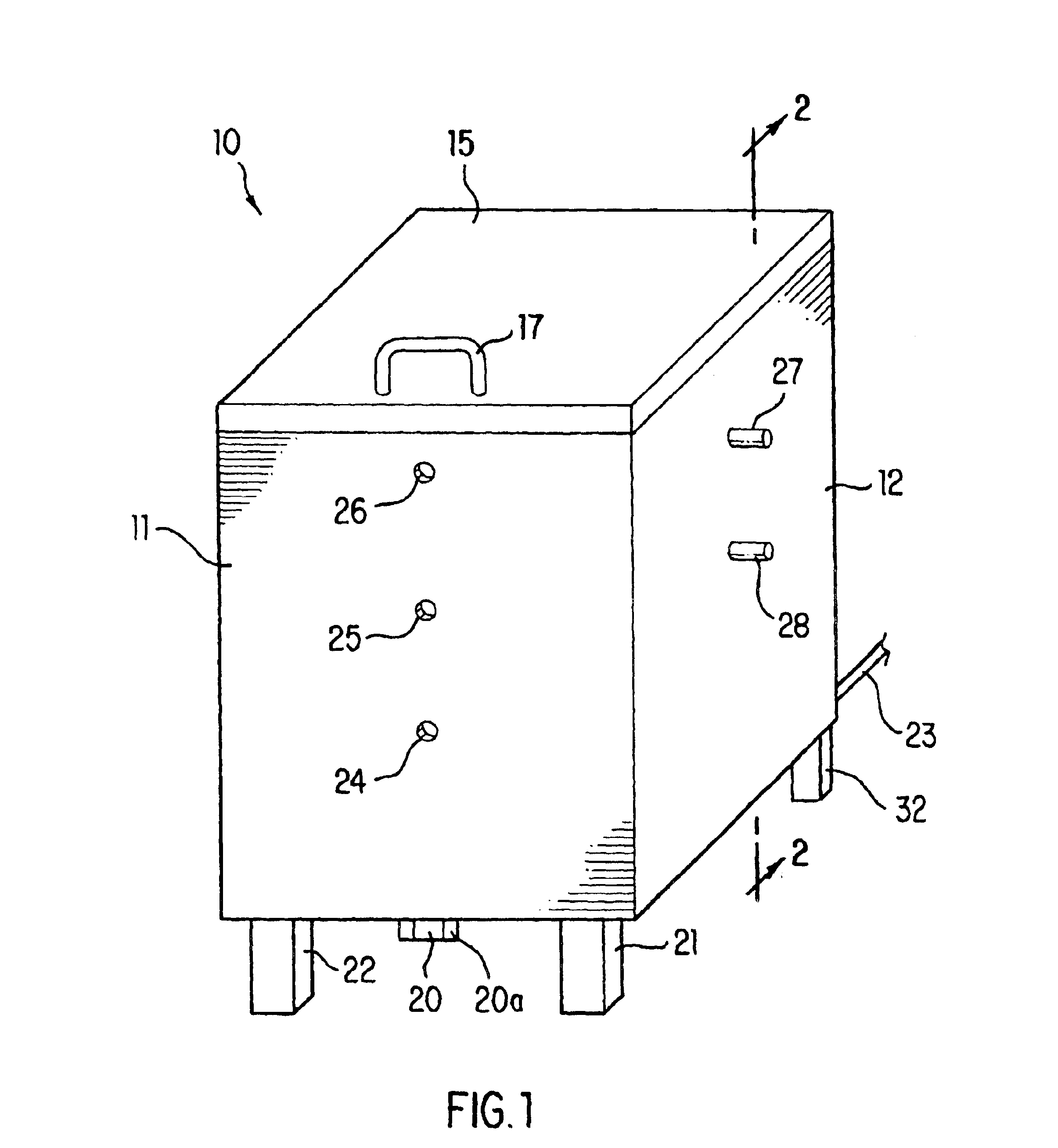
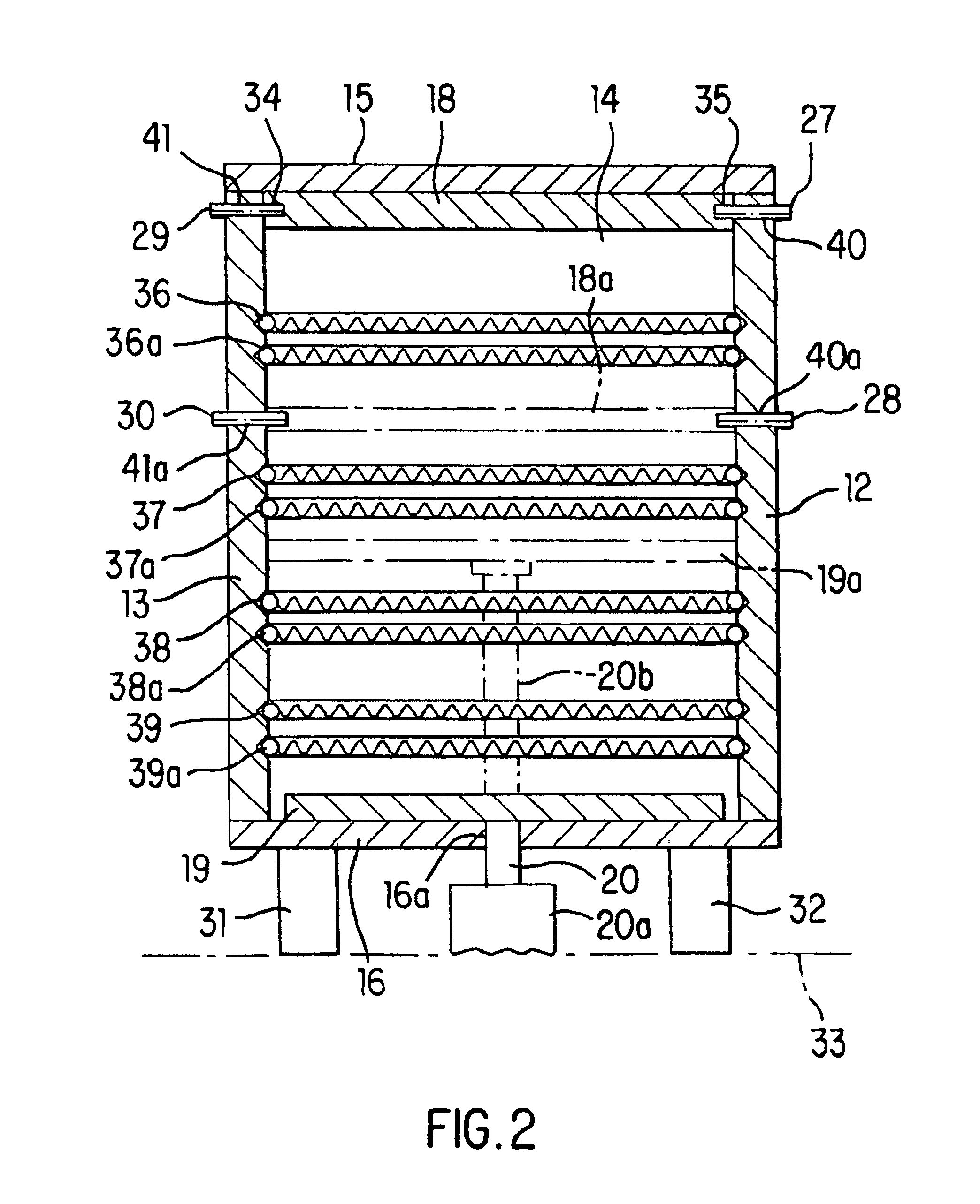
An inventory of items bearing reference numerals is:

Numeral Item Description 10 kiln 11 front wall 12 side wall 13 side wall 14 back wall 15 top 16 bottom wall 16a hole in bottom wall for ram 17 top handle 18 moveable top wall 18a alternate moveable top wall position 19 moveable bottom wall 19a alternate moveable bottom wall position 20 ram 20a hydraulic cylinder 20b alternate ram position 21 front leg 22 front leg 23 electric power source 24 peep hole 25 peep hole 26 peep hole 27 peg 28 peg 29 peg 30 peg 31 rear leg 32 rear leg 33 floor level 34 hole in edge of moveable wall 35 hole in the edge of moveable wall 36 electrical heating element 36a auxiliary heating element 37 electrical heating element 37a auxiliary heating element 38 electrical heating element 38a auxiliary heating element 39 electrical heating element 39a auxiliary heating element 40 hole in side wall 40a hole in side wall 41 hole in side wall 41a hole in side wall 50 base surface 51 support member 52 support member...


PUM


Abstract

This is an electrically heated ceramic kiln and a method for varying the size of the kiln chamber by moveable top and/or bottom walls which can be moved vertically within the kiln chamber, together with a new method of insulating the kiln and providing captive air chambers about the kiln.

Description

BACKGROUND OF THE INVENTIONI. Field of the InventionThis invention is in the general field of electrically heated ceramic kilns;The invention is more particularly directed to a method and apparatus for effective firing of different size kiln loads within a single kiln, in which adjustments of kiln size and electrical element use maximizes the effective use of electrical energy. Additionally a system for enhanced performance is provided with a unique captive air system.II. Description of the Prior ArtA major problem in the firing of ceramic articles has been the problem of firing small loads of product in larger kilns. Many kiln users wish to use a large kiln for efficient firing. However, the problem is that a kiln cannot be operated efficiently and properly with less than a full load. Therefore, many kiln users either must delay firing smaller loads until a full load can be accumulated or must have a variety of kiln sizes.In the past there have been limited attempts to manufacture ...

Claims


Application Information

Patent Timeline
IPC IPC(8): F27B1/00F27B5/00F27D1/12F27D1/00F27B5/08F27B1/12F27B17/00F27D1/04
CPCF27D1/04F27B17/0041Y02P40/60
Inventor CRESS, STEVEN B.
Owner CRESS STEVEN B
Why Eureka
Try Eureka