Condensing device and method for condensing moisture in a vehicle battery

Active Publication Date: 2014-01-16
ROBERT BOSCH GMBH
View PDF21 Cites 1 Cited by
  • Summary
  • Abstract
  • Description
  • Claims
  • Application Information

AI Technical Summary

Benefits of technology

[0010]The condensing device is preferably surrounded by a porous material, wherein the condensing device is in physical contact with the porous material. It is advantageous here that

Problems solved by technology

It is a known fact that batteries or accumulators in vehicles, especially motor vehicles, such as automobiles, are generally exposed to environmental influences, e.g. moisture, which penetrates into the interior of the battery and can cause corrosion or short circuits there, possibly leading not only to destruction of the battery but also, in some circumstances, to damage to electric loads fed by the battery (e.g. a vehicle control unit, which is relatively sensitive to voltage spikes that can arise in the event of a short circuit within the battery).
Even if the battery is protected from being sprayed directly with water, this generally being due to the arrangement of the battery in the vehicle, relatively high air humidi

Method used


Image

  • Condensing device and method for condensing moisture in a vehicle battery
  • Condensing device and method for condensing moisture in a vehicle battery
  • Condensing device and method for condensing moisture in a vehicle battery

Examples


Example

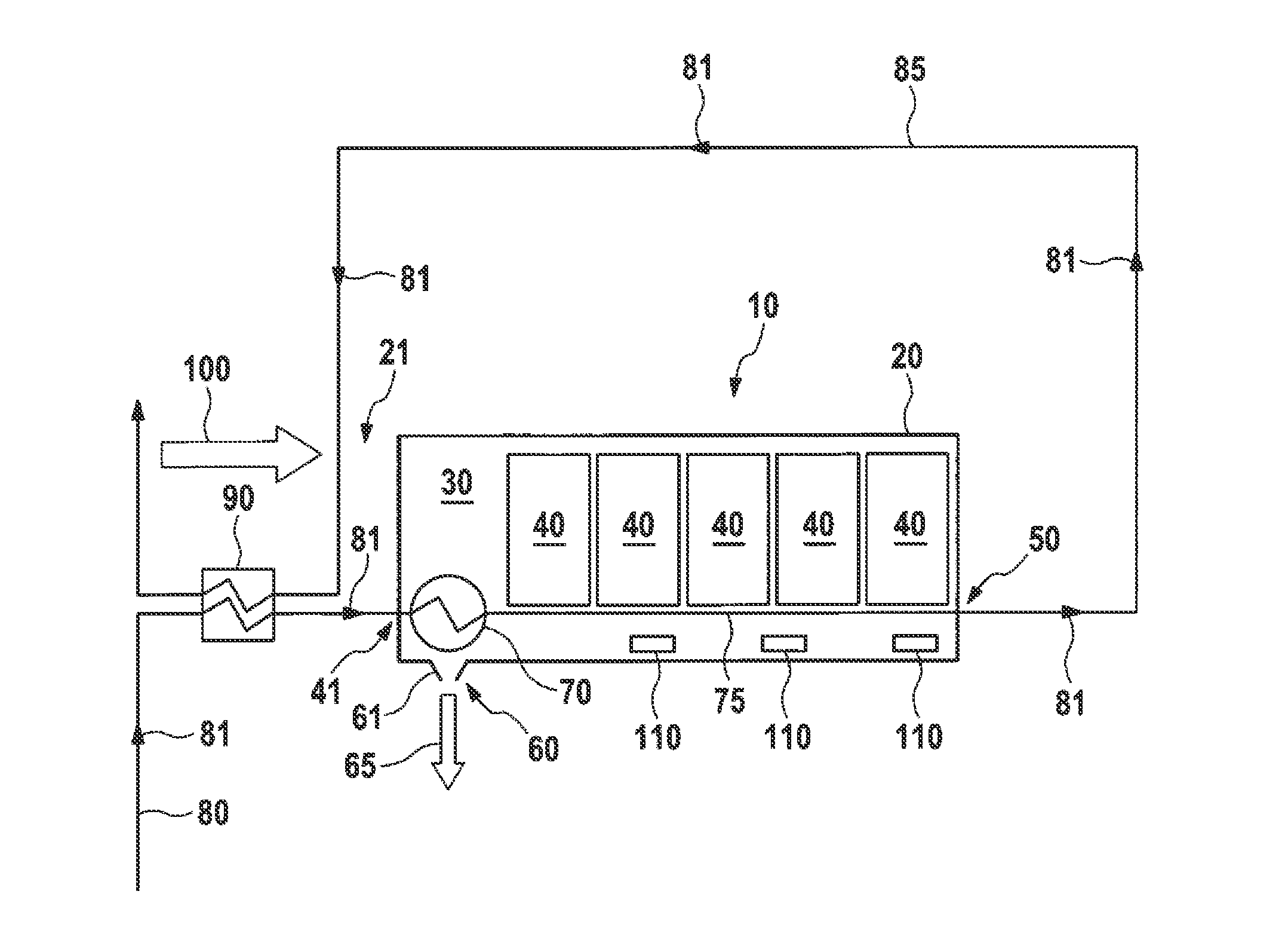
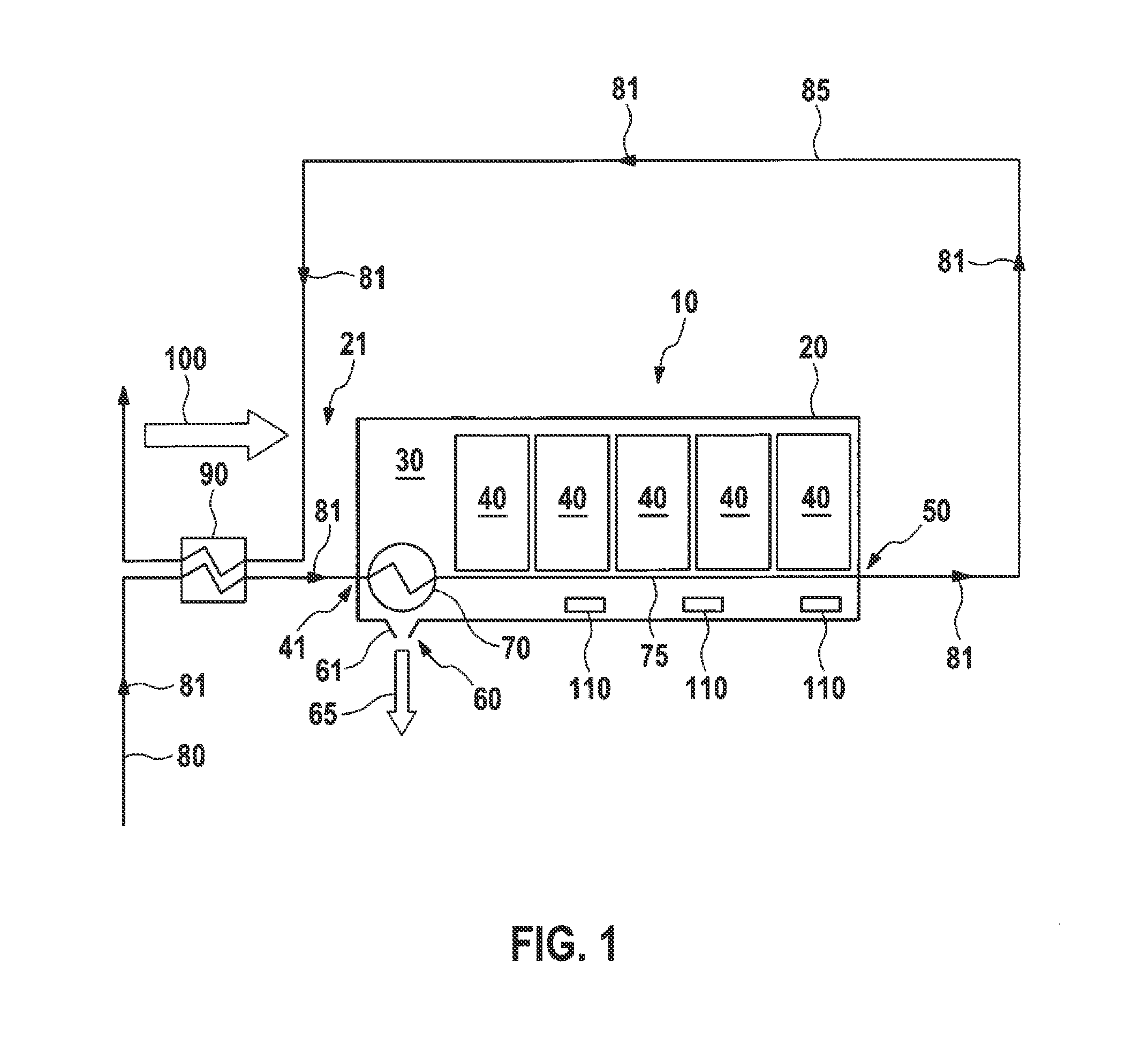
[0016]FIG. 1 shows, schematically, a battery 10 having a battery housing 20, in the battery interior 30 of which there is a plurality of accumulator cells or battery cells 40. Arranged in the battery housing 20 is an inlet opening 40 (not shown specifically), a first outlet opening 50 and a second outlet opening 60, the exact operation of which will be explained later.

[0017]Arranged in the battery interior 30 is a condensing device 70 (as it were a “condensate trap”), which is part of a cooling circuit 80 of a vehicle (not shown here), e.g. an automobile. The cooling circuit 80 is preferably a cooling circuit of an air conditioning system of the vehicle.

[0018]Cooling fluid flowing in the cooling circuit 80 in the direction of the arrows 81 flows initially into a cooling unit or heat exchanger 90 (also referred to as a “chiller”) in that section of the cooling circuit 80 which is illustrated in FIG. 1, and, from there, flows through the inlet opening 40 into the condensing device 70,...


PUM


Abstract

A condensing system for a battery in a vehicle and a method for condensing moisture in a battery are provided. In one embodiment, the condensing system includes a battery housing, which surrounds a battery interior. At least one battery cell is arranged in the interior. An inlet opening is arranged in the battery housing, for a cooling fluid entering the battery interior. A first outlet opening and a second outlet opening are both arranged in the battery housing. The first outlet opening is in fluid communication with the cooling fluid emerging from the battery interior. A condensing device is arranged in the battery interior and is in fluid communication with the cooling fluid and causes moisture present in the battery interior to condense. The condensed moisture emerges into the environment through the second outlet opening.

Description

BACKGROUND OF THE INVENTION[0001]The present invention relates to a condensing device and to a method for condensing moisture in a vehicle battery, in particular in a vehicle battery in a motor vehicle, such as an automobile.[0002]It is a known fact that batteries or accumulators in vehicles, especially motor vehicles, such as automobiles, are generally exposed to environmental influences, e.g. moisture, which penetrates into the interior of the battery and can cause corrosion or short circuits there, possibly leading not only to destruction of the battery but also, in some circumstances, to damage to electric loads fed by the battery (e.g. a vehicle control unit, which is relatively sensitive to voltage spikes that can arise in the event of a short circuit within the battery).[0003]Even if the battery is protected from being sprayed directly with water, this generally being due to the arrangement of the battery in the vehicle, relatively high air humidity can cause these unwanted p...

Claims


Application Information

Patent Timeline
IPC IPC(8): H01M10/50B60L50/64
CPCH01M10/5004H01M10/613H01M10/625H01M2220/20H01M10/6568H01M10/663B60L50/64H01M50/249Y02E60/10Y02T10/70Y02T90/16
Inventor HEYSE, JOERGEITNER, PETER
Owner ROBERT BOSCH GMBH
Why Eureka
Try Eureka