Whistle having air flow converter

a technology of air flow and whistle, which is applied in the field of whistle, can solve the problems of not being able to continue blasting for a long time, the volume cannot be changed, and the sound is difficult to hear in a noisy place, and achieves the effect of pleasing and attractive sound

Inactive Publication Date: 2005-01-04
MOLTEN CORPORATION
View PDF16 Cites 18 Cited by
  • Summary
  • Abstract
  • Description
  • Claims
  • Application Information

AI Technical Summary

Benefits of technology

A whistle of the invention is characterized by an air flow converter for converting or varying the flow of air passed from an air passage towards the sound outlet of the whistle, thereby creating, and enhancing, extra higher harmonics.
Because of this structural duality of the whistle, two sounds generated by the respective edges in combination with the resonance chambers incorporate different higher harmonics formed in the respective resonance chambers when they come out of the two sound outlets. The resultant superposed sound may beat producing a pleasant and attractive sound to the ear, which helps attract attention of people hearing the whistle.

Problems solved by technology

In this whistle, although the tone is alterable, its volume cannot be changed, unless a great amount of air is quickly breathed in.
However, lung capacity, i.e. an amount of air that a person can breathe at a time, greatly varies from person to person, so that a person having a smaller lung capacity can produce only a small whistle sound, especially when he is not familiar with whistling, and then the sound is difficult to hear in a noisy place.
If such a person could give a large blast on a whistle, he would not be able to continue blasting for a long time.
It is therefore difficult for him to blow a whistle loudly.

Method used


Image

  • Whistle having air flow converter
  • Whistle having air flow converter
  • Whistle having air flow converter

Examples


Embodiment Construction

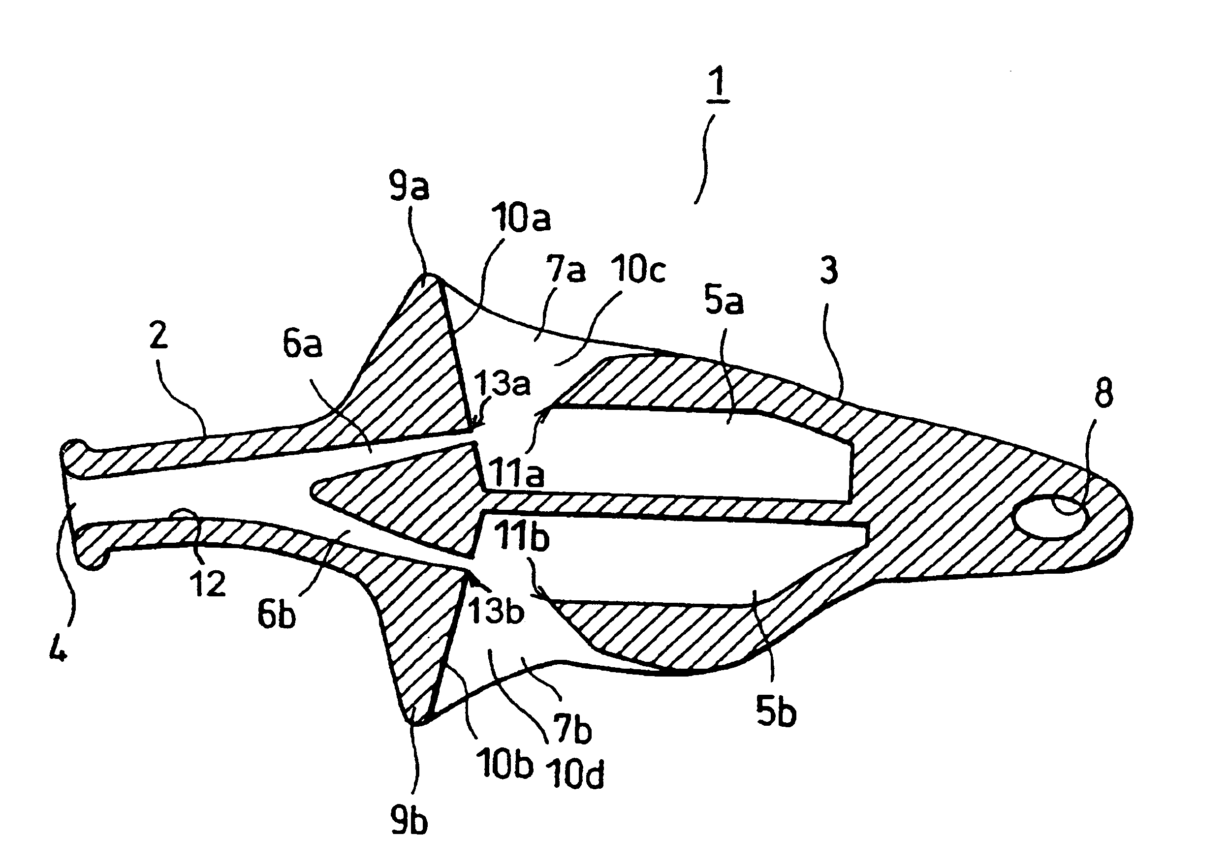
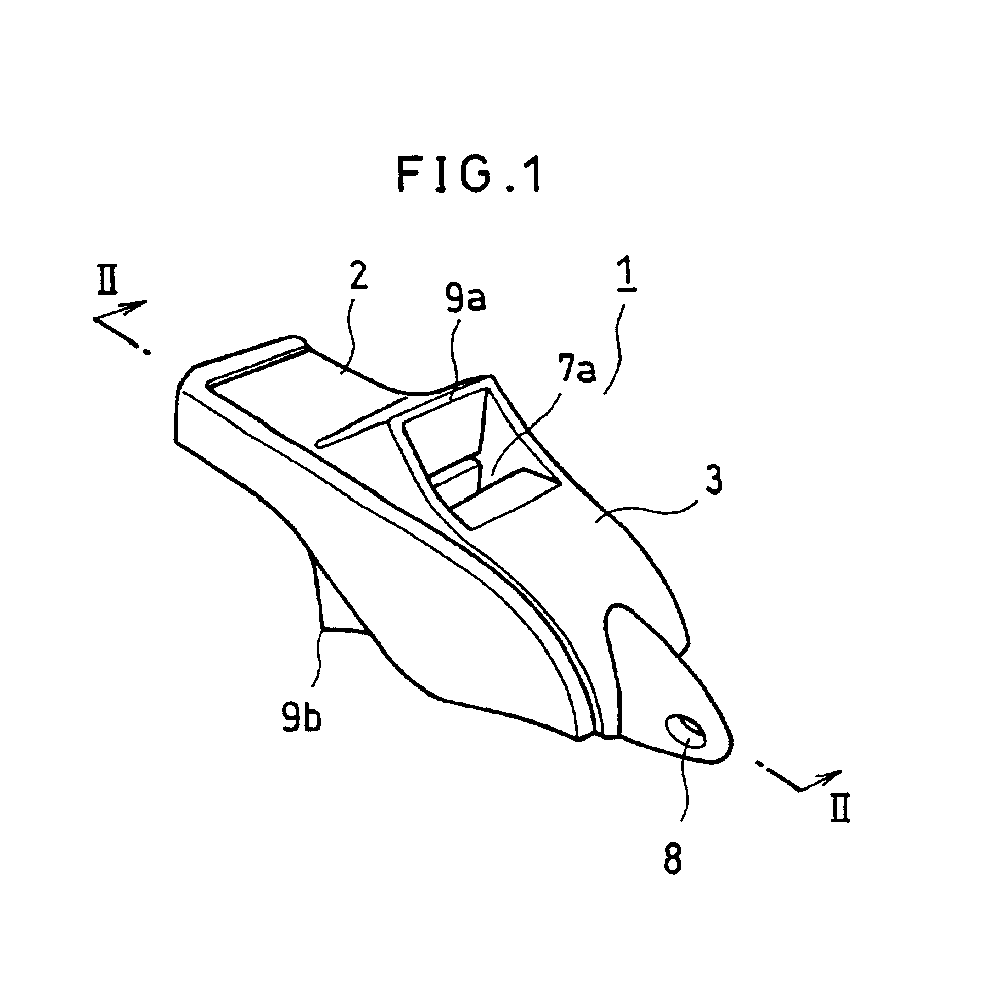
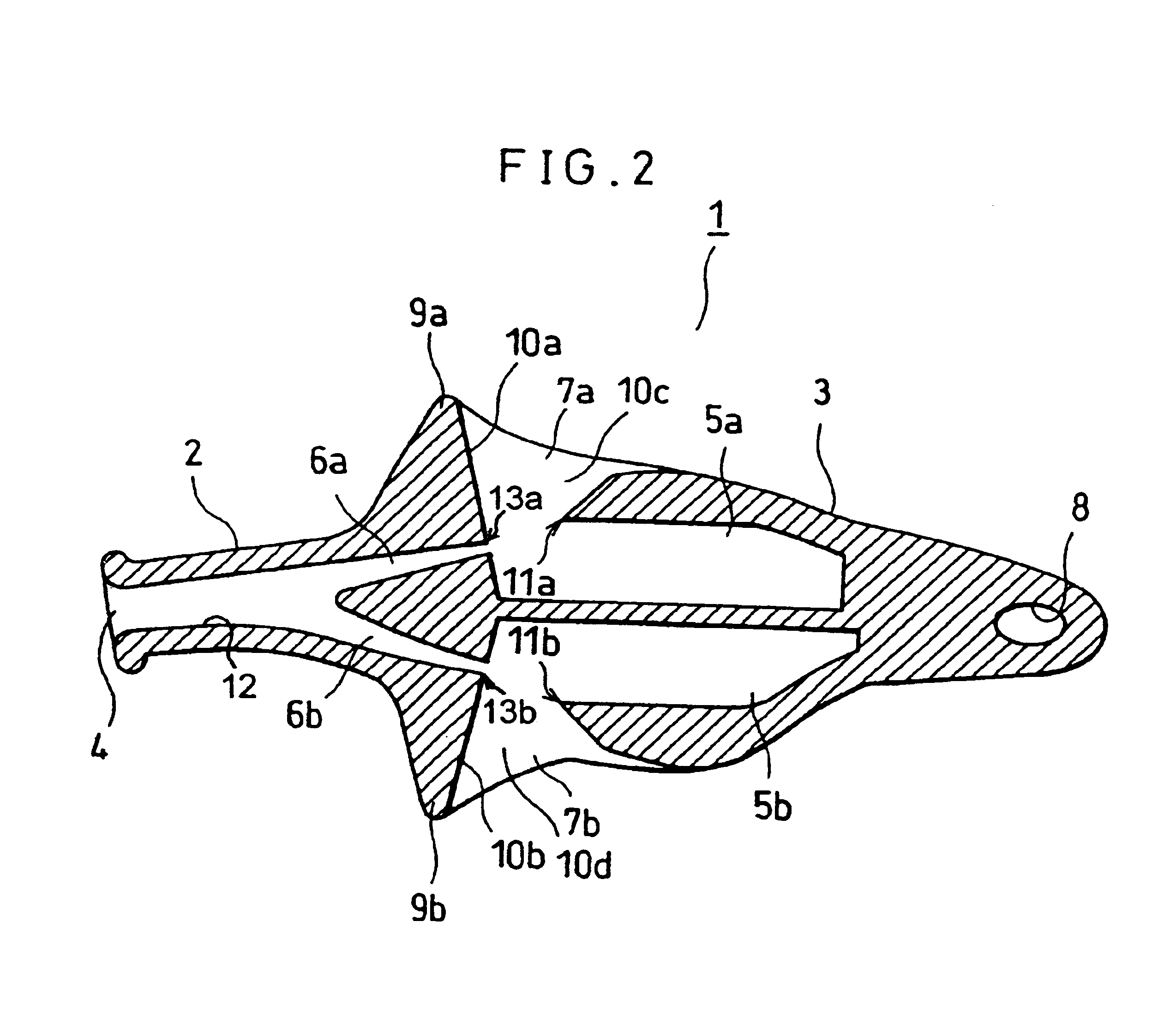
Referring now to FIGS. 1 and 2, there is shown a whistle 1 of the invention, which includes a mouthpiece 2, which has an interior mouthpiece wall 12, and a resonance section 3, both integrally formed by molding a plastic. The mouthpiece 2, adapted to be placed between the lips of a person blowing the whistle, has an elongate rectangular air inlet 4 for receiving his breath. The resonance section 3 includes a first upper and a second lower resonance chambers 5a and 5b, respectively, in the form of cylindrical cavities. The whistle has a first and a second sound outlets 7a and 7b, respectively, which are openings formed between the resonance chambers 5a and 5b and a first and a second air passages 6a and 6b, respectively, bifurcating from the air inlet 4. A hole 8 is formed at the end of the resonance section 3 for passing therethrough a hanging strap.

Wall shaped first and second air flow converters 9a and 9b each form part of a first and a second sound outlet 7a and 7b, respectively....


PUM


Abstract

A whistle (1) has: a mouthpiece which includes an air inlet (4); a first and a second resonance chambers (5a, 5b) to which air is injected through the air inlet via a first and a second air passages (6a, 6b); a first and a second sound outlets (7a, 7b) in the form of openings formed between the air passages and the resonance chambers; and a first and a second air flow converters (9a, 9b) for varying the flow of air between the air passages and the sound outlets. The air flow converters (9a, 9b) are each part of the sound outlets, and have walls (10a, 10b) which are perpendicular to the air passages (6a, 6b). The air flow converters (9a, 9b) create extra higher harmonics, increase sound pressures in the resonance chambers, and shorten rising time of the whistle, so that the whistle quickly produces loud harmonious beats, which is effective to call attention of people.

Description

FIELD OF THE INVENTIONThe invention relates to a whistle for use in umpirage of athletic games and in security jobs including guiding and signaling to gathering people.BACKGROUND OF THE INVENTIONWhistles are used by judges in sport tournaments for example, in signaling a start, breaks, resumption, and the end of a game, and warnings the players to follow the rules of the game. Whistles are based on a fundamental principle that an edge tone is produced by an edge inside a whistle when air is blown into the mouth (air inlet) of the whistle and that the edge tone is then amplified by resonance in a resonance chamber of the whistle.An example of such whistles is disclosed in Japanese Patent Laid Open Publication No.8-211881. This publication teaches a whistle having a mouthpiece into which air is blown, a duct for passing the air to an edge and a resonance chamber where the blown air oscillates in resonance with an edge tone, and a sound outlet in the form of opening formed between the ...

Claims


Application Information

Patent Timeline
Patent Type & Authority Patents(United States)
IPC IPC(8): G10K5/00
CPCG10K5/00
Inventor TANAKA, MASAYUKI
Owner MOLTEN CORPORATION
Why Eureka
Try Eureka