
Multiple contents container assembly for ultrapure solvent purging
a multi-container, ultrapure technology, applied in the direction of liquid cleaning, liquid handling, packaging goods, etc., can solve the problems of low volatility and ineffective use of low-volatile chemicals, and achieve the effects of reducing end-user interaction, reducing labor intensity, and reducing labor intensity
- Summary
- Abstract
- Description
- Claims
- Application Information
AI Technical Summary
Benefits of technology
Problems solved by technology
Method used
Image

Examples
second embodiment
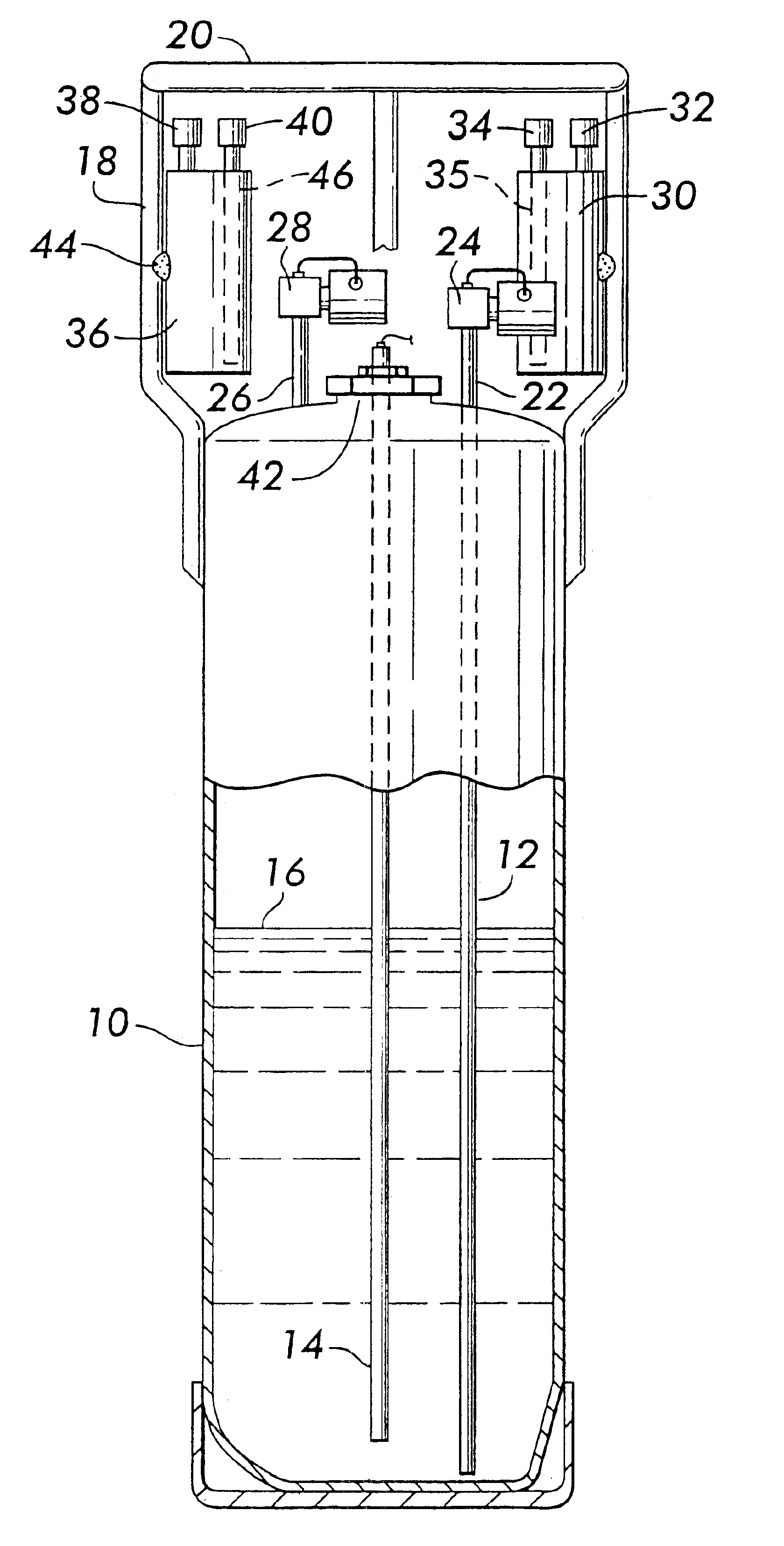
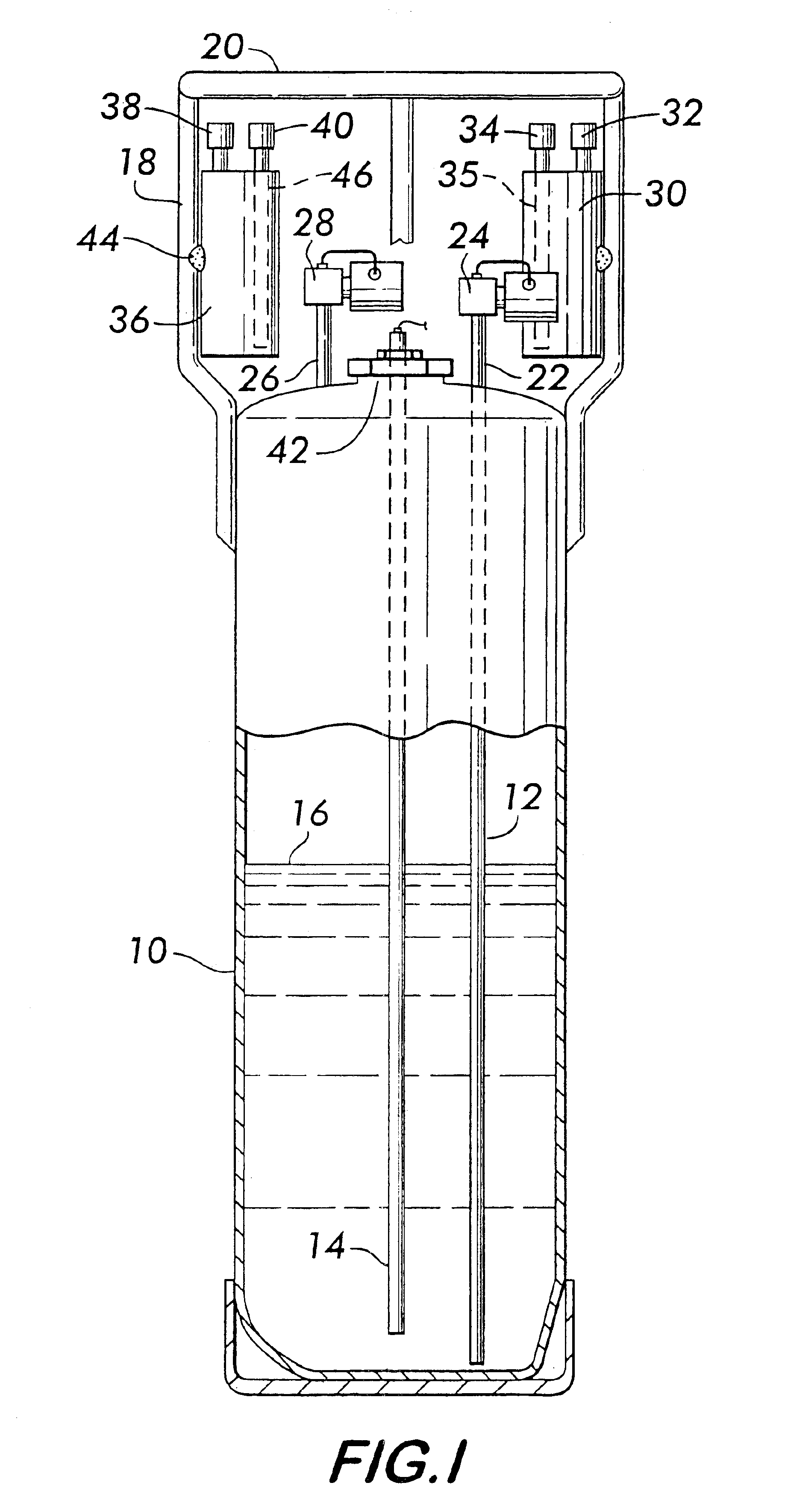
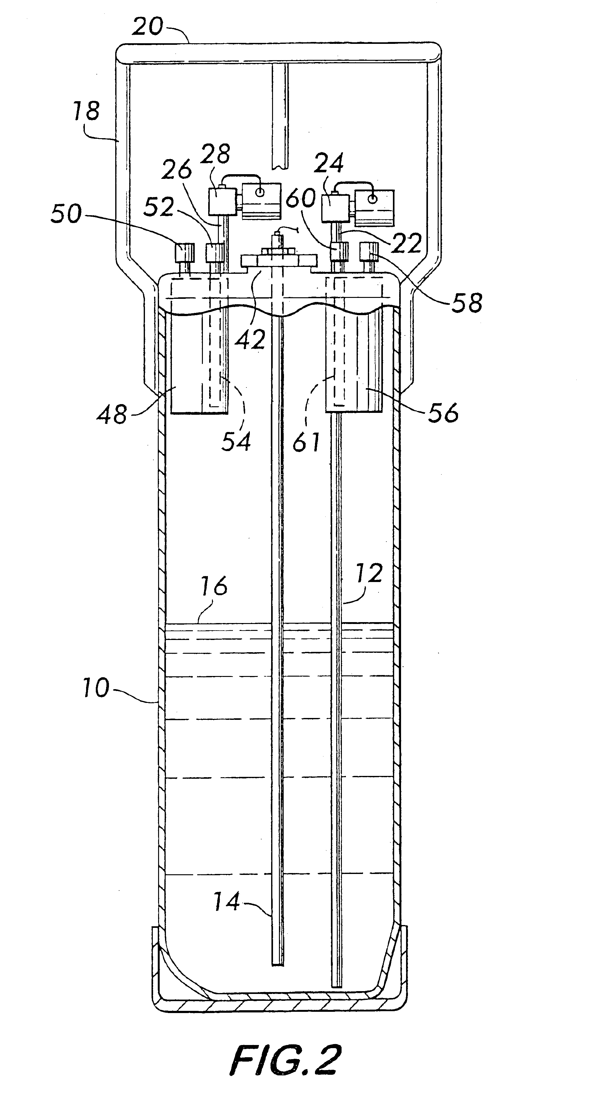
With reference to FIG. 2, common parts are labeled with the same part numbers as FIG. 1 and will not necessarily be repeated in this description of this second embodiment showing the ampoules situated in the interior of the container 10. The source chemical solvent ampoule 48 has an inlet 50 and an outlet 52 that function similarly to the assembly of FIG. 1, with outlet 52 having an integral diptube 54. Used solvent from ampoule 48 after passing through the manifold, not shown, is recovered in the interiorly situated solvent capture ampoule 56, which has an inlet 58 and outlet 60, which operate in a manner consistent with the assembly of FIG. 1. Outlet 60 may have a diptube 61, if desired.
third embodiment
With reference to FIG. 3, common parts are labeled with the same part numbers as FIG. 1 and will not necessarily be repeated in this description of this third embodiment showing a baffled 64 ampoule 62 having discrete solvents 88 and 90 or a solvent in one ampoule 66 and an empty ampoule 68 or sorbent filled ampoule 68. Either ampoule 66 and 68 could serve either function depending only on connection to the manifold and programming of the automated control unit. Ampoule 68 is outfitted with an inlet 74 and an outlet 72, the latter of which is integral to a diptube 70 for liquid out service. Pressurizing gas would be administered through inlet 74. Ampoule 66 being below ampoule 68 has a diptube 76 and 80, respectively, connected to each of its inlet 78 and outlet 82. The extent of any diptube or the existence of such a diptube is dependent on whether the ampoule is being used for solvent such as dual solvent delivery or whether it is being use as the solvent capture ampoule, with or ...
PUM
| Property | Measurement | Unit |
|---|---|---|
| purity | aaaaa | aaaaa |
| pressure | aaaaa | aaaaa |
| vacuum | aaaaa | aaaaa |
Abstract
Description
Claims
Application Information