Popcorn machines and methods of making and using the same

Inactive Publication Date: 2015-03-26
PARAMOUNT PICTURES
View PDF18 Cites 0 Cited by
  • Summary
  • Abstract
  • Description
  • Claims
  • Application Information

AI Technical Summary

Benefits of technology

This patent provides a modular construction for popcorn machines that allows for easy shipping and assembly by customers. The unique configurations of the popcorn machines have modular components that require minimal assembly. This reduces the risk of damage and the cost associated with shipping and assembly of a fully assembled machine. The modular components can be grouped in higher density configurations to decrease the risk of breakage and avoid the need for a truck with a lift. The patent also presents improved housing constructions that facilitate cleaning, servicing, and personalization of the machine. The advantageous constructions address shortcomings of previous popcorn machines and enhance the machine's ability to attract attention.

Problems solved by technology

Such complete assembly of a popcorn machine by the manufacturer, however, generally presents an apparatus to be shipped to a customer that essentially represents a fairly heavy, large and awkward, glass-sided box that can create at least three issues relating to shipping.
First, this tends to result in high shipping costs because some freight is priced based on the cubic dimensions of the container, and a fair amount of the machine represents a large, somewhat empty enclosure.
Second, this tends to result in high shipping costs because the resulting large, heavy, awkward container used to ship a completely assembled machine requires shipment by a truck that has a rear lift.
Third, shipping a completely assembled machine tends to result in higher overall costs due to warranty claims because the vertical glass side panels of the machine are difficult to protect and are subjected to increased likelihood of breakage during shipment.
Given the common use of cardboard and other non-rigid materials for the outer walls of shipping containers for popcorn machines, the risk of glass breakage or other damage to the upper or base units can be significant.
Thus, from a shipping standpoint, a completely assembled machine is problematic, yet it is believed that this indeed is the way in which all such popcorn machines presently are being shipped.
Current assembled popcorn machines also typically present several difficulties to an operator.
This can be difficult, as the operator must reach through the machine to reach the opposed side walls, the ceiling (or bottom surface of the upper unit) and the floor of the cavity (or top surface of the base unit).
This is still more problematic because popcorn machines commonly have kettle assembly supports that are fixedly mounted to the ceiling of the cavity (or bottom surface of the upper unit) and which extend downward to suspend the kettle assembly within the cavity.
Therefore, they present awkward obstacles to cleaning the surfaces within the cavity and may have fairly sharp edges that can present a hazard or risk of injury when inadvertently contacted by a user.
The fixed location of the kettle assembly supports, suspending the kettle assembly close to the ceiling and near the middle of the cavity, also tends to make it difficult for an operator to reload the kettle assembly with fresh cooking oil and corn to repeat the popping process.
Reaching into the machine when surfaces may be hot, and manipulating the lid of the kettle assembly and the containers that hold the contents to be added to the kettle assembly, can be awkward and potentially hazardous, if an operator is not particularly attentive and careful.
An additional issue may arise when an operator experiences a problem with a kettle assembly that loses its ability to heat the oil and corn.
An electrical malfunction or failure may be related to failure of a fuse, fusible link or thermostat within a kettle assembly.
When experiencing an electrical malfunction within a kettle assembly, such as a burned out fusible link or thermostat, there typically is no provision for disassembly to readily access and replace electrical components.
Thus, such a failure commonly results in the need to replace the entire kettle assembly, even though the vast majority of the kettle assembly components otherwise would continue to be in useful condition.
The need to replace an entire kettle assembly not only presents a cost issue for an operator, but also a convenience issue because a new kettle assembly must be ordered and delivered, before the popcorn machine can be used again.
These types of lighting schemes are quite common, have been used for decades, and for this reason do not tend to attract the attention desired.

Method used


Image

  • Popcorn machines and methods of making and using the same
  • Popcorn machines and methods of making and using the same
  • Popcorn machines and methods of making and using the same

Examples


Embodiment Construction

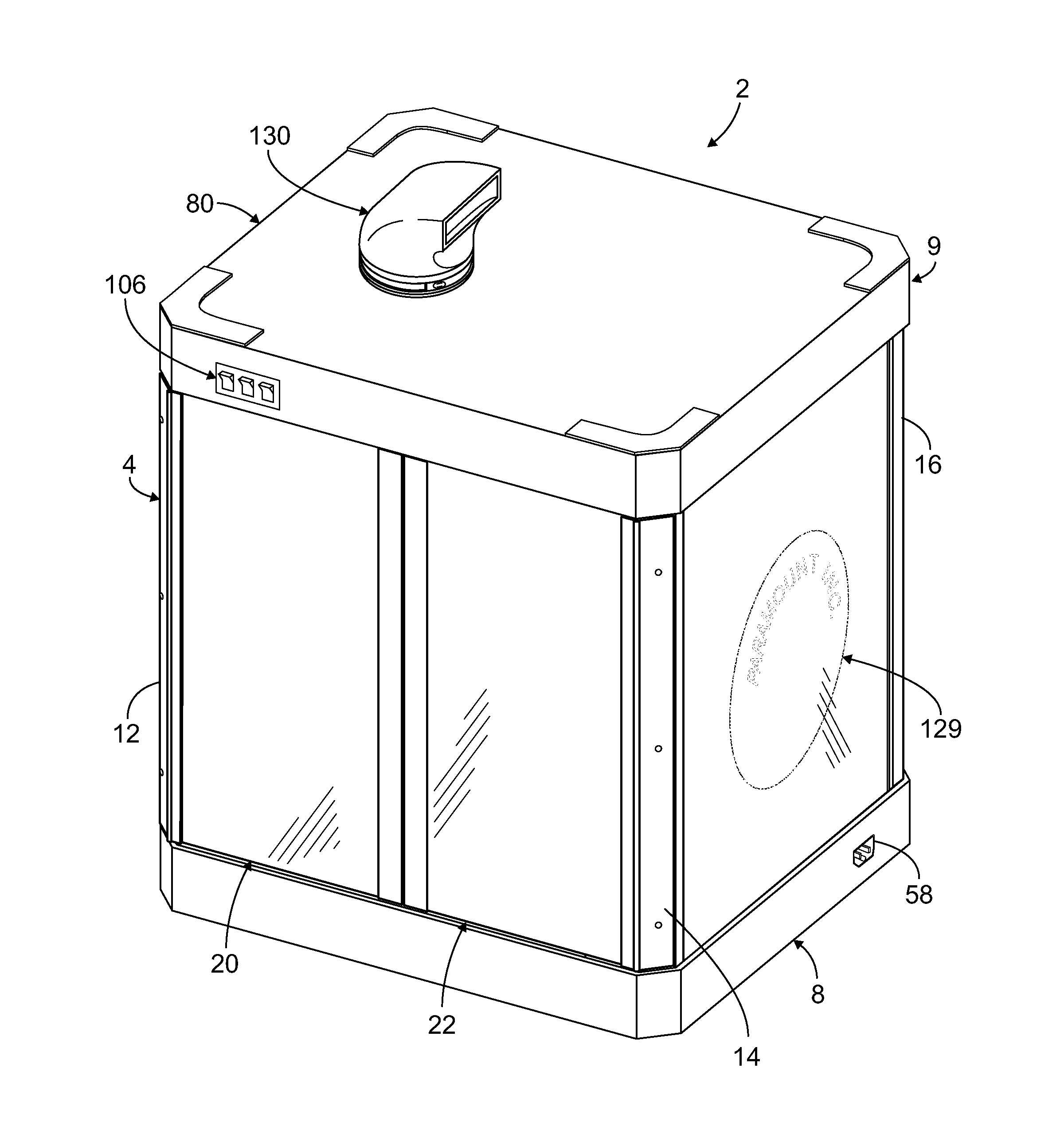
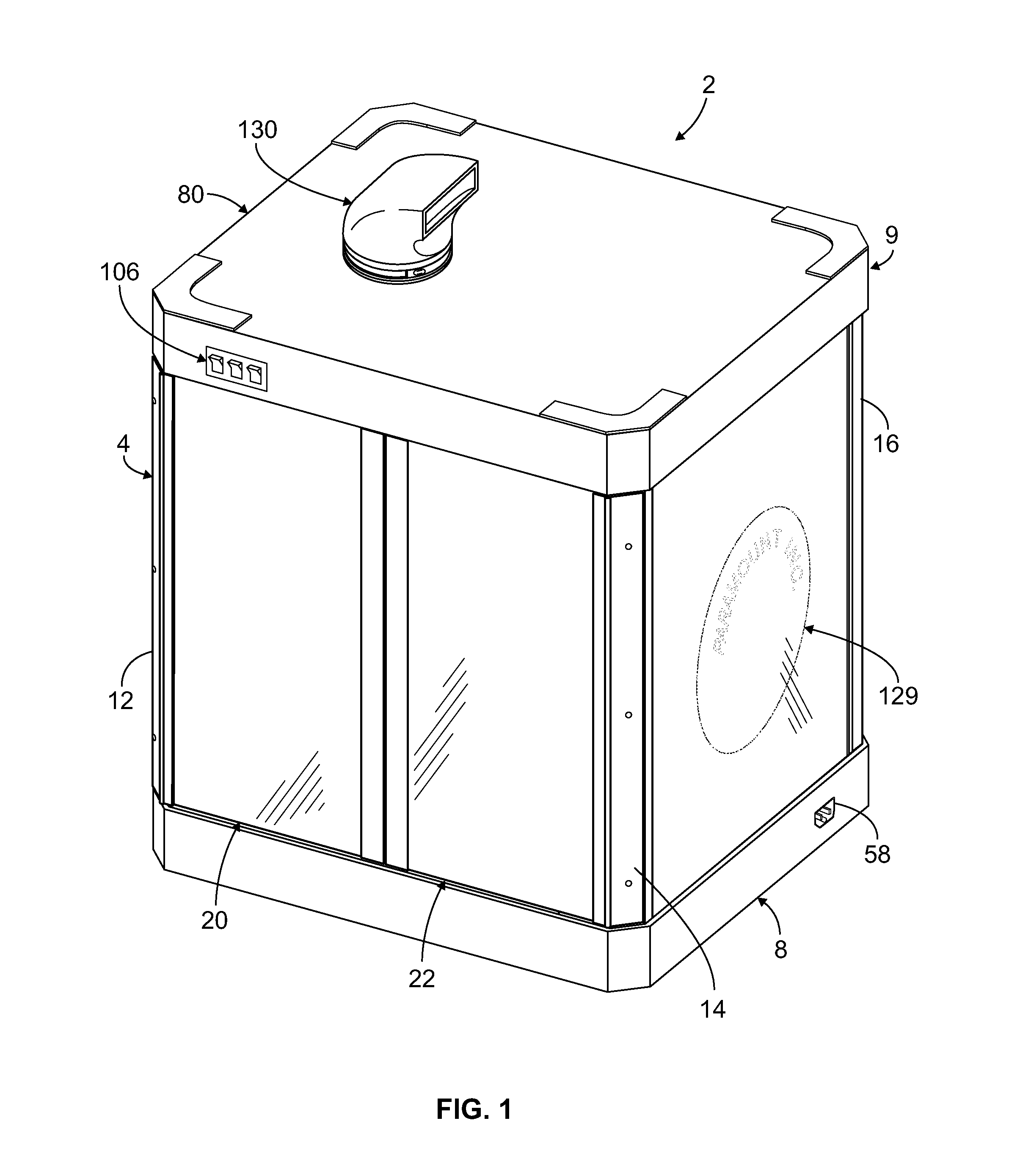
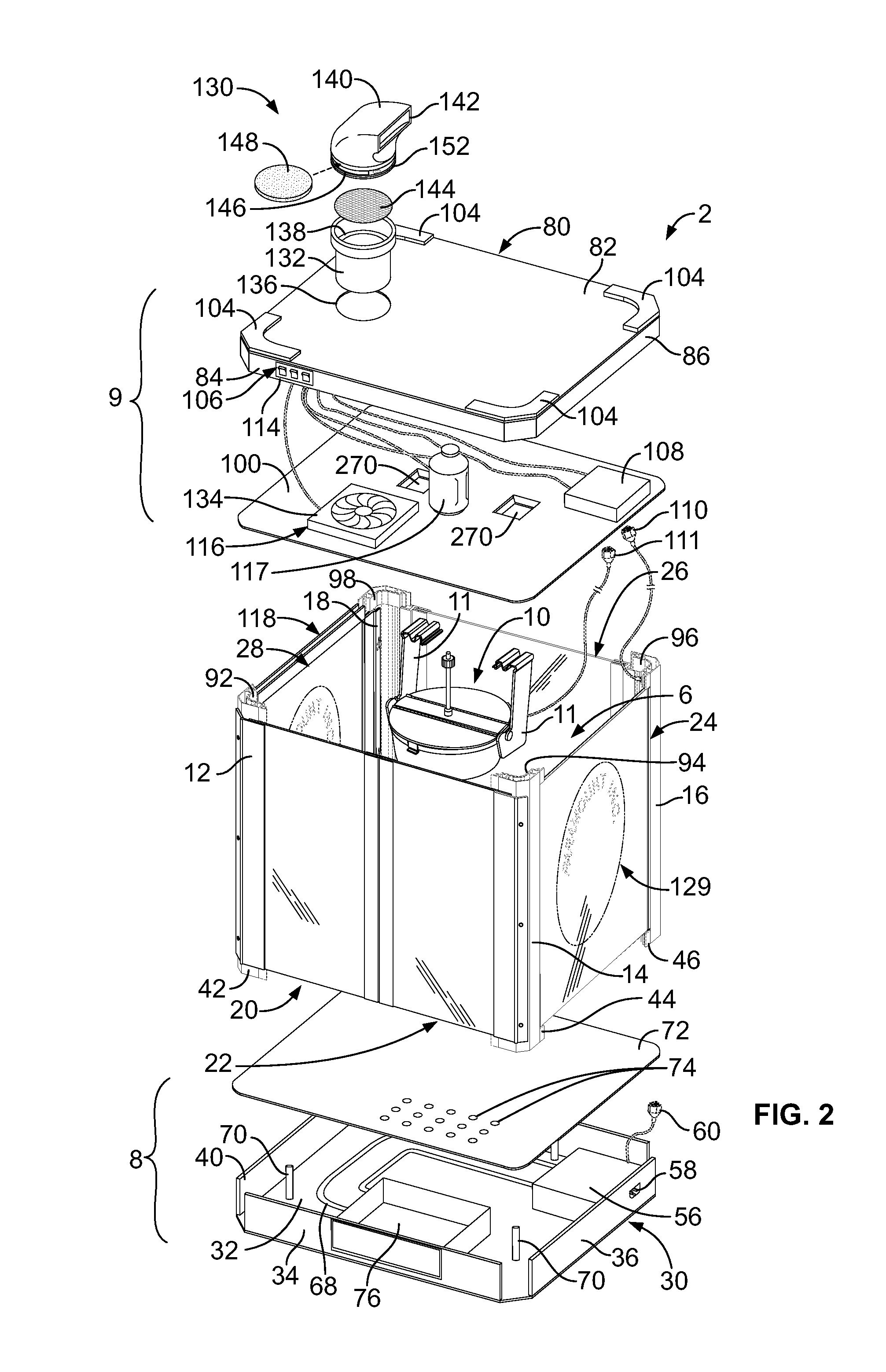
[0076]Referring generally to FIGS. 1-47, it will be appreciated that popcorn machines of the present disclosure generally may be embodied within numerous configurations, having one or more advantageous features relative to prior art machines. Indeed, while acknowledging that all example configurations that may include the various advantageous features of popcorn machines and methods of making and using such machines need not be shown herein, it is contemplated that popcorn machines may incorporate various combinations of the advantageous features taught herein. To demonstrate this position, the first example popcorn machine includes several, but not all, of the inventive features disclosed herein.

[0077]Turning to FIGS. 1-10 and 13-22B, a first example popcorn machine 2 is illustrated. The popcorn machine 2 includes a housing 4, defining a cavity 6. The housing 4 has a base unit 8 and an upper unit 9. The base and upper units may be made of suitable materials, which may include stamp...


PUM


Abstract

Popcorn machines are disclosed having a construction that includes an upper unit spaced from and above a base unit and a plurality of columns that are spaced apart and slidably connected to the upper and base units thereby defining a cavity, wherein such popcorn machines include a first side having an opening through which the cavity is accessible and at least a second side having an opening through which the cavity is accessible. Side panels having vertical rails and a portion of a hinge along one side and a latch along another side, and a configuration of a popcorn machine having edge lighting, are disclosed.

Description

BACKGROUND OF THE INVENTION[0001]1. Field of the Invention[0002]The present invention generally relates to corn popping apparatus, such as popcorn machines, and more particularly to structural improvements relating to the assembly, use and maintenance of popcorn machines and components thereof.[0003]2. Discussion of the Prior Art[0004]Corn popping apparatus may take various forms, but when intending to make repeated batches of popped corn, it is common to utilize what generally is known as a popcorn machine, with such a machine having a housing or cabinet, which includes a cavity in which a heated kettle assembly is located to pop the corn and in which the popped corn is at least collected and temporarily stored. The housing may include glass or transparent side panels through which the kettle assembly and popped corn within the cavity may be viewed. This may serve to drive desirability for the popped corn, while also displaying the quantity of popped corn available. Indeed, the des...

Claims


Application Information

Patent Timeline
IPC IPC(8): A23L1/18
CPCA23L1/1812A47J37/0629A23P30/38A23L7/183
Inventor JOHNSON, ROBERT A.JOHNSON, NATHANPIEROWAY, HAROLD RAYMONDLENZEN, NICHOLAS J.
Owner PARAMOUNT PICTURES
Why Eureka
Try Eureka