
Scanning apparatus and method

a three-dimensional object and scanning apparatus technology, applied in the field of scanning apparatus and methods, can solve the problems of difficult scanning of real-world, three-dimensional objects, difficult line of sight, high cost of cnc machines, etc., and achieve the effect of reducing time and cost of generating and quickly scanning the surface of objects

Inactive Publication Date: 2007-12-25
3D SCANNERS LTD
View PDF26 Cites 129 Cited by
  • Summary
  • Abstract
  • Description
  • Claims
  • Application Information

AI Technical Summary

Benefits of technology

"The present invention provides a scanning apparatus for quickly and accurately creating a computer model of an object using a wide range of applications. The apparatus uses structured light to scan the surface of the object and capture data from multiple points simultaneously. The data is then combined to create the model, which can be displayed in real-time. The apparatus is efficient and cost-effective, with time and cost reductions of an order of magnitude compared to conventional techniques. Additionally, the apparatus can capture color data and map it onto the model. The scanning means can be mounted on various types of manual machines for flexibility in scanning. Overall, the invention provides a more efficient and cost-effective way to create computer models of objects."

Problems solved by technology

Real-world, three-dimensional objects, whether with natural form (e.g., geographical, plant, human, or animal-like) or man-imagined form (e.g., sculptures, reliefs, cars, boats, planes, or consumer products) are difficult to scan.
This is because of features such as rapidly varying surface normals and surfaces for which a line of sight is difficult because it is partially obscured by other parts of the object.
CNC machines are expensive, partly because of the incorporation of motors and the associated equipment for assuring precision motion, such as linear guides and drive screws.
Even when a CNC machine has six degrees of freedom, it is often not sufficiently flexible so as to position the probe to scan the complete surface of the object without colliding with the object.
When the object is a person or expensive, the risk of using a CNC machine may be unacceptable, and there would be a necessity to make a machine to meet both the safety and scanning requirements of the application.
The programming of a CNC machine so that the surface of the object is completely scanned without a collision of the probe or machine with the object is often highly complex.
Usually, the design of the machine and the degrees of freedom inherent in the design and limitations in the probe design, such as the standoff distance during scanning between the probe and the object, mean that it is impossible to come up with a scanning strategy that will scan the complete surface of the object.
Horizontal arm machines have the disadvantage of not being able to easily orient the probe in six degrees of freedom.
The limited flexibility in the design of a horizontal arm machine makes most of the far side of the object unscannable.
The sparseness and lack of organization of the points make it difficult to provide enough information for constructing a computer model of the object that is of acceptable quality.
In general, if a larger working volume is required, the arms become very expensive, less accurate and tiring, and difficult to operate.
The limited working volume can be increased by leapfrogging, in which the whole arm / base is moved to access another volume; but this requires a time-consuming system of registering at least three points each time the arm is moved and recombining the data sets from each arm position.
These devices are prone to generating scanned points with very large errors.
Some devices cannot work when the object being scanned has metallic components.
There are differences between the methods in terms of accuracy and cost, but these do not generalize with category.
Structured light using stripe or area methods is not good at capturing independent feature points because there is no way for the operator to align a known point on the object with a point on the stripe or in the area.
Geometrical errors in the scanning process stem from many sources.
One major disadvantage in normal use is that from any given demand for a frame, there is a variability of 40 msecs until the start of capture of that frame.
If the probe is being moved at, for example, 100 mm / sec, this can lead to a geometrical error of 4 mm in the probe's data.
One major disadvantage in normal use is that if the probe is being moved with a slow shutter speed, an additional geometrical error is created.
This can also introduce a geometrical error when the probe is moving.
The total variabilities of the CCD camera and the arm can cause large aggregate errors.
Moving from unstructured point representation to polygon or complex surface formats often produces large compressions but relies on approximations, so the process is nearly always irreversible.
It is also difficult to automate so as to give good enough results.
As an intermediate data structure, it has disadvantages in that the intermediate data structure does not record the orientation of each stripe; it does not record breaks in the data, but assumes that all the points are connected by a surface; and it does not record jumps in the data, such as those caused by occlusions.
The method is very slow, requires skill, patience, and concentration, and is expensive in human time—particularly for large, detailed objects that can take three weeks to scan.
However, the “polygonization” of unorganized data points is usually very slow, and speed decreases significantly as the number of points increases.
The results are usually so poor as to be unacceptable.
There is usually a significant amount of hand editing of the data required.
The process is not automatic and requires a combination of operator guidance and automated execution of algorithms.
This process is not accurate and is followed by an automatic least squares fitting process that attempts to adjust the position and orientation of each range image such that they fit together as well as possible.
This process is lengthy, often taking hours on a powerful computer.
The process is expensive, both in terms of capital equipment cost and people time.
The display of points has the disadvantage of easily becoming confusing to interpret, and also that the observer does not know when parts of the object's surface have been missed during scanning.

Method used


Image

  • Scanning apparatus and method
  • Scanning apparatus and method
  • Scanning apparatus and method

Examples


Embodiment Construction

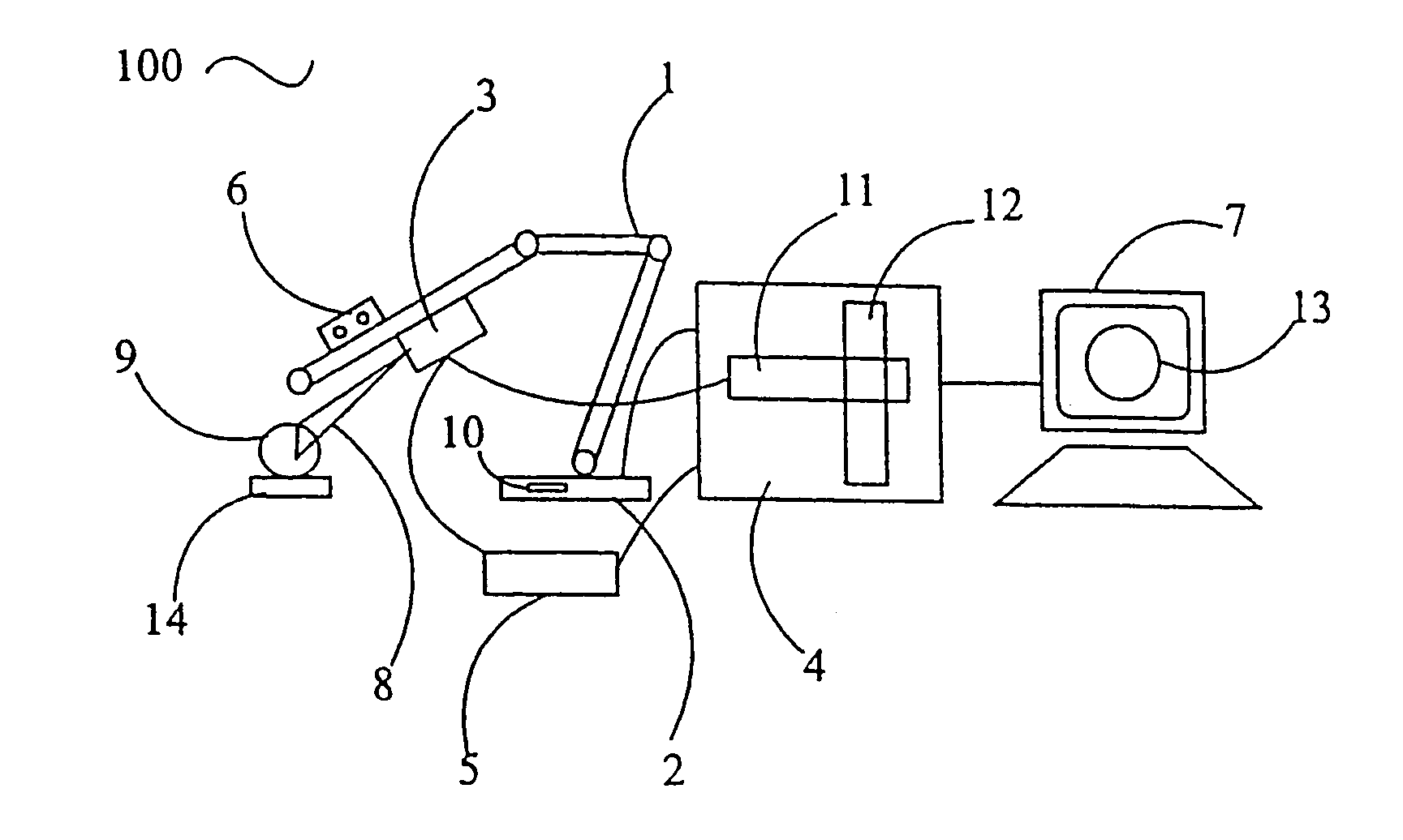
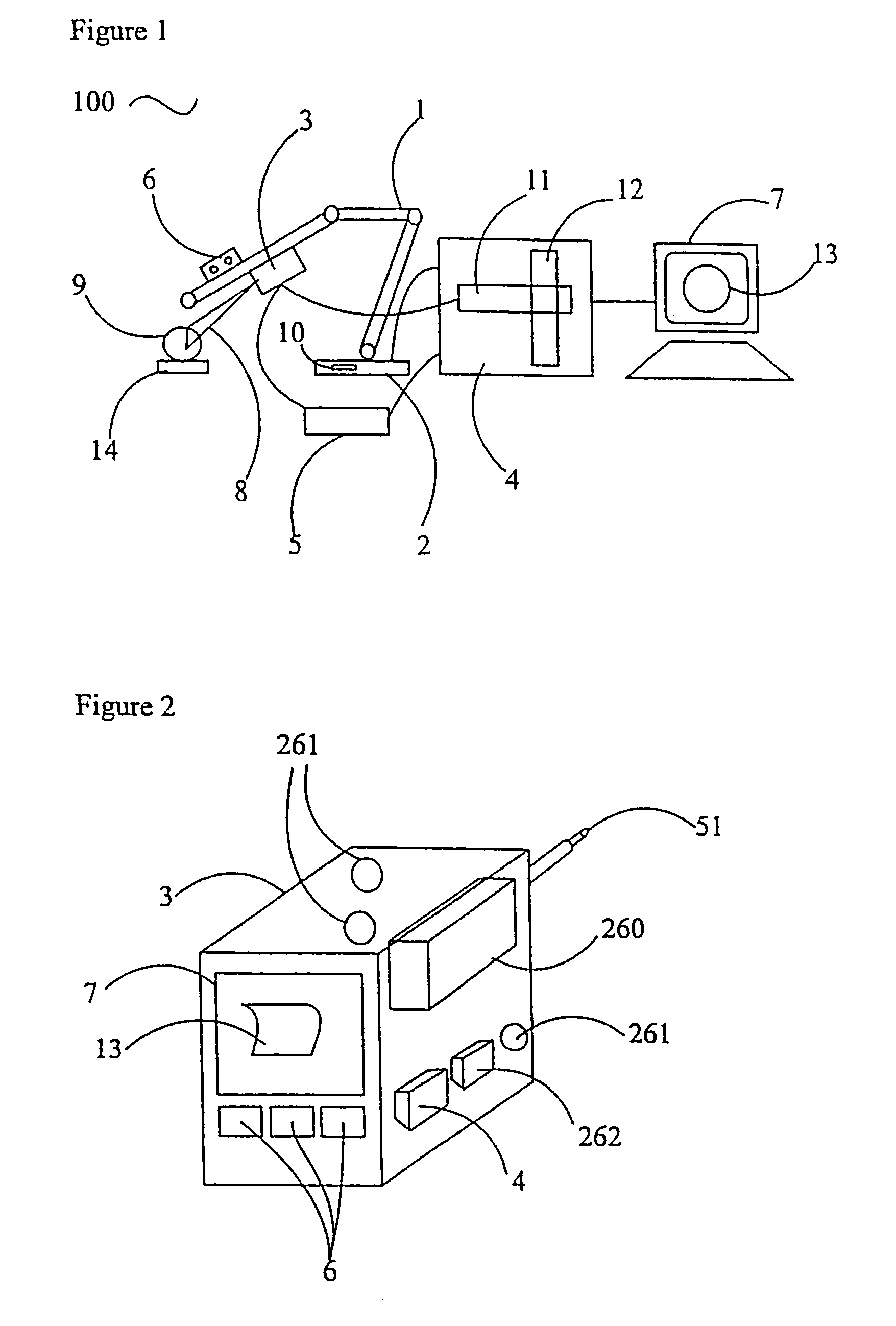
[0080]Referring now to FIG. 1, a scanning apparatus 100 comprises a multiply-jointed arm 1 with an arm control unit 2 and a probe 3. The control unit 2, which includes a processing unit 10, is coupled to a computer or processing unit 4 and color monitor 7. The probe 3 is also coupled to a probe control unit 5 that is likewise coupled to the computer 4. The intermediate data is displayed on the color monitor 7 as rendered polygons 13. The probe 3 provides a stripe 8, which is projected onto an object 9 positioned on a turntable 14. The stripe 8 is in the form of a plane of light. Buttons 6 are also provided to control data capture. A color frame grabber 11 in the computer 4 is mounted on a standard bus 12 and coupled to the probe 3.

[0081]The computer 4, probe control unit 5, arm control unit 2, buttons 6, color frame grabber 11, and monitor 7 are provided separately. For example, the computer 4 and monitor 7 may be a personal computer and VDU, although for certain applications, it ma...


PUM


Abstract

A scanning apparatus and method for generating computer models of three-dimensional objects comprising means for scanning the object to capture data from a plurality of points on the surface of the object so that the scanning means may capture data from two or more points simultaneously, sensing the position of the scanning means, generating intermediate data structures from the data, combining intermediate data structures to provide the model; display, and manually operating the scanning apparatus. The signal generated is structured light in the form of a stripe or an area from illumination sources such as a laser diode or bulbs which enable data for the position and color of the surface to be determined. The object may be on a turntable and may be viewed in real time as rendered polygons on a monitor as the object is scanned.

Description

CROSS-REFERENCES TO RELATED APPLICATIONS[0001]This application is a continuation of U.S. patent application Ser. No. 09 / 000,215, filed on May 26, 1998, now U.S. Pat. No. 6,611,617, which is a 371 of international application PCT / GB96 / 01868, filed Jul. 25, 1996, which in turn claims the benefit of British Application No. 9515311.0, filed Jul. 26, 1995.FIELD OF THE INVENTION[0002]This invention relates to an apparatus and method for scanning a three-dimensional object.BACKGROUND OF THE INVENTION[0003]Real-world, three-dimensional objects, whether with natural form (e.g., geographical, plant, human, or animal-like) or man-imagined form (e.g., sculptures, reliefs, cars, boats, planes, or consumer products) are difficult to scan. This is because of features such as rapidly varying surface normals and surfaces for which a line of sight is difficult because it is partially obscured by other parts of the object.[0004]Scanning machines—also known as digitizing machines—for scanning objects o...

Claims


Application Information

Patent Timeline
Patent Type & Authority Patents(United States)
IPC IPC(8): G06K9/00G01B11/25G01B11/24
CPCG01B11/2518
Inventor CRAMPTON, STEPHEN JAMES
Owner 3D SCANNERS LTD
Learn More