Server monitoring virtual points of presence

a server and virtual point technology, applied in the field of server monitoring virtual points of presence, can solve the problems of inhibiting or delay the reporting of performance data, high cost of setting up and maintaining agent computers in many different geographic regions, and monitoring service providers incur costs for maintaining the security of agent computers, etc., to reduce the likelihood of delays or omissions in reporting, and the cost of setting up and maintaining the monitoring system is significantly reduced

Inactive Publication Date: 2005-12-06
MICRO FOCUS LLC
View PDF22 Cites 116 Cited by
  • Summary
  • Abstract
  • Description
  • Claims
  • Application Information

AI Technical Summary

Benefits of technology

[0008]The present invention overcomes the above and other problems by setting up the automated agents (agent computers and software) in one or more centralized locations or “data centers” rather than deploying the agents at each of the desired PoPs. The message traffic (HTTP requests, etc.) generated by the centrally located agents is transmitted over special links to the desired Internet connection points (referred to as “virtual points or presence”), which are typically geographically remote from the agents. Upon reaching the virtual points of presence, the message traffic flows onto the Internet. The client requests appear to the servers to emanate from users that are local to the virtual PoPs. Because there is no need to deploy and maintain automated agents or other monitoring components at the virtual PoPs, the cost of setting up and maintaining the monitoring system is significantly reduced.
[0009]In a preferred embodiment, the links used to interconnect the centrally located agents to the remote virtual PoPs are preferably dedicated connection-oriented links, such as Asynchronous Transfer Mode (ATM) or CLEAR Line™ links, that provide a known or determinable latency. The remote side of each such link is preferably peered directly to the Internet (typically by a regional ISP). The centrally located agent(s) associated with a given virtual PoP is / are configured with the unique IP addresses of the virtual PoP, so that TCP / IP traffic between the agent(s) and the server system is forced through the virtual PoP to and from the Internet. To determine a server response time as seen from a virtual PoP location, an agent measures the overall response time as observed from the agent location (data center) and deducts the round-trip delay associated with the path between the agent and the virtual point of presence. The latency associated with this extra path may alternatively be ignored. The response times and any other performance data generated by the agents is preferably aggregated within a database that is local to the agents, reducing the likelihood of delays or omissions in reporting of observed performance data.

Problems solved by technology

A significant problem with the above approach is that the cost of setting up and maintaining agent computers in many different geographic regions is very high.
The monitoring service provider may also incur costs for maintaining the security of the agent computers, and for upgrading the agent software as new versions become available.
Another problem with the existing approach is that problems with the Internet can inhibit or delay the reporting of performance data by the agent computers.
As a result, the web site operator may not learn about a particular performance problem until well after the problem has been detected.

Method used


Image

  • Server monitoring virtual points of presence
  • Server monitoring virtual points of presence
  • Server monitoring virtual points of presence

Examples


Embodiment Construction

[0016]The following description sets forth numerous implementation-specific details of a system for monitoring the performance of a web site or other Internet server system. These details are provided in order to illustrate a preferred embodiment of the invention, and not to limit the scope of the invention. The scope of the invention is defined only by the appended claims.

[0017]Throughout the description, the term “monitoring” will be used to refer generally to both continuous monitoring (e.g., accessing the server system once per hour) and to short term testing (e.g., load testing of a deployed or pre-deployed server system). Example components and methods that can be used to load test a web site or other server system over the Internet are described in above-referenced application Ser. No. 09 / 484,684.

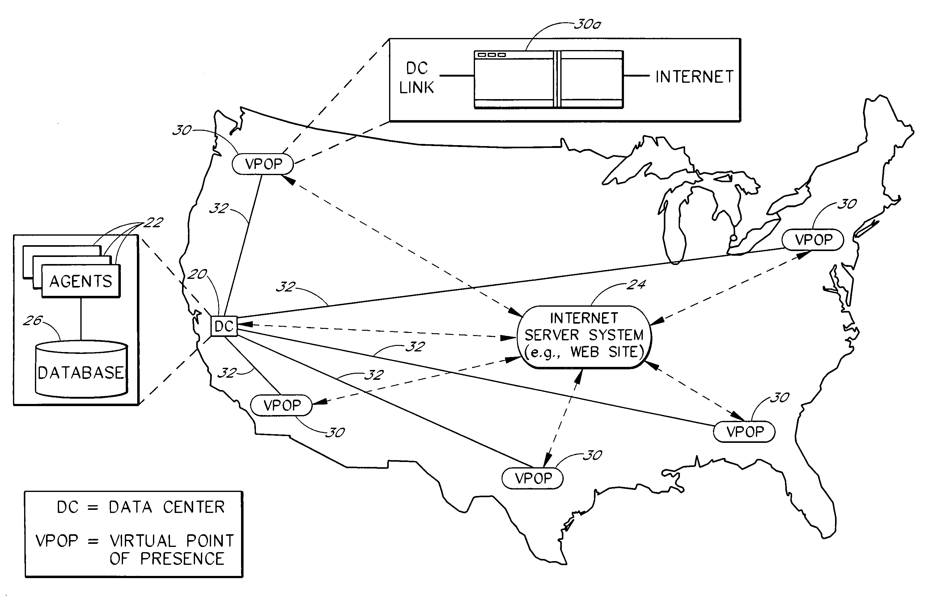
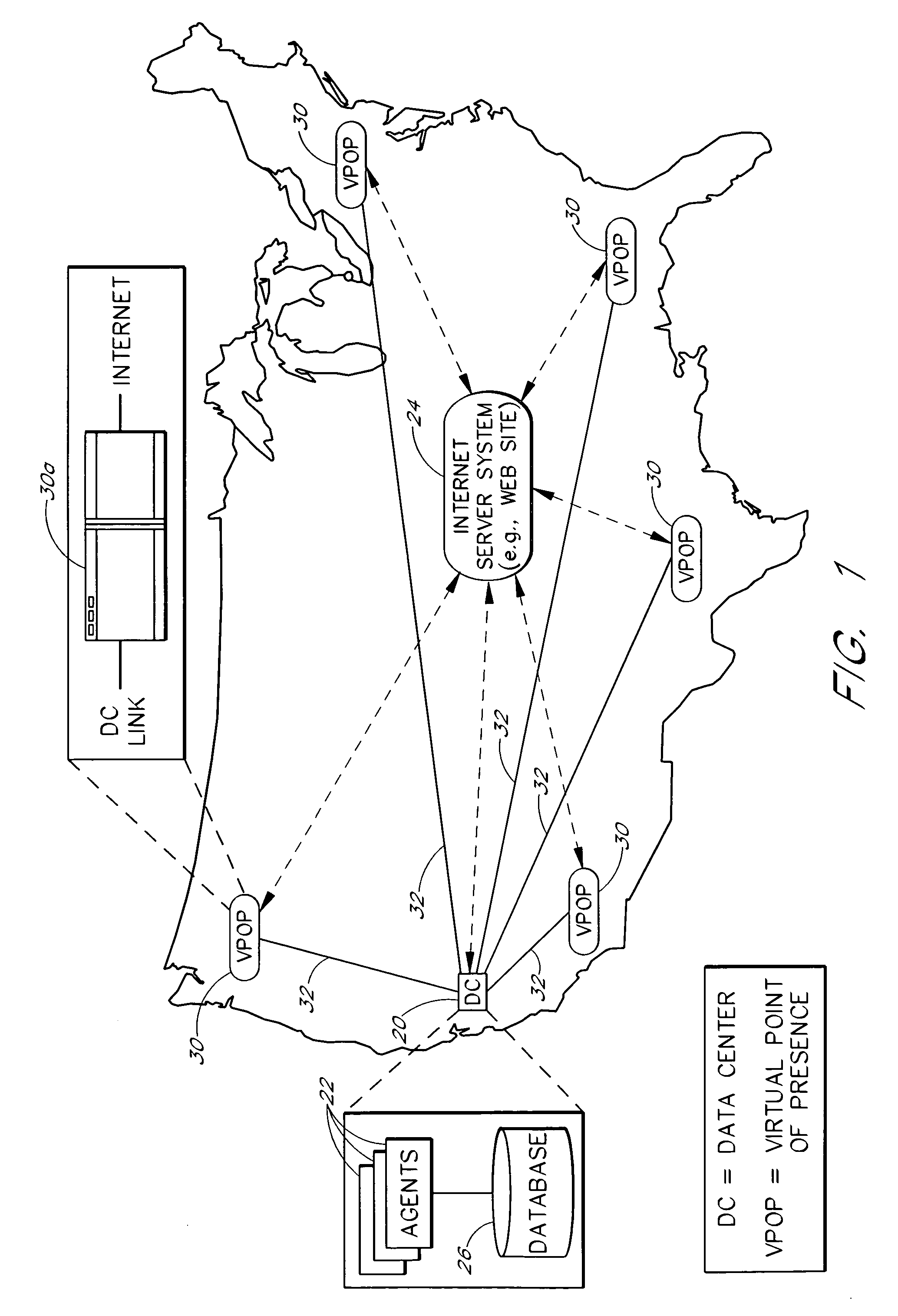
[0018]FIG. 1 illustrates the general architecture of an example monitoring system according to the present invention. The monitoring system includes a data center 20 that hosts the a...


PUM


Abstract

A server monitoring system monitors the performance of a web site or other Internet server system, as seen by users in multiple geographic access locations, without the need for special monitoring software or hardware within such locations. Automated agents that run at a central data center generate message traffic that is used to access and monitor the server system from the multiple remote locations. The message traffic associated with a particular remote access location is transmitted from the data center to the remote location across a dedicated link, such as an ATM link, and is routed onto the Internet at a corresponding Internet access point. The server response to each request message flows back to the data center across the same link as the corresponding request message. The remote access points thus serve as virtual points of presence for monitoring purposes. Server response times as seen from the remote access locations are determined by measuring the total response times as observed from the data center, and deducting from the total response times the round-trip latencies associated with the corresponding dedicated links. The response times and other performance data generated by the agents are aggregated within a database that is local to the agents. Multiple data centers may be interconnected such that each data center services a particular continent or other region using a respective set of virtual points of presence.

Description

RELATED APPLICATIONS[0001]This application relates generally to the subject matter described in the following co-pending U.S. patent applications, the disclosures of which are hereby incorporated herein by reference in their entirety: application Ser. No. 09 / 484,686, titled POST-DEPLOYMENT MONITORING OF SERVER PERFORMANCE, filed Jan. 17, 2000, now U.S. Pat. No. 6,449,739 and application Ser. No. 09 / 484,684, titled SERVICE FOR LOAD TESTING A TRANSACTIONAL SERVER OVER THE INTERNET, filed on Jan. 17, 2000, now U.S. Pat. No. 6,477,483.FIELD OF THE INVENTION[0002]The present invention relates to methods for monitoring the operation of a web site or other server system as experienced from multiple user locations on a computer network such as the Internet.BACKGROUND OF THE INVENTION[0003]The performance of a web site or other Internet server system, as experienced by end users of the system, can vary significantly depending on the geographic locations of the users. For example, users in Lo...

Claims


Application Information

Patent Timeline
Patent Type & Authority Patents(United States)
IPC IPC(8): G06F11/34H04L12/24G06F15/00H04L12/26
CPCG06F11/3495H04L12/2602H04L41/046H04L43/00G06F11/3414G06F2201/875H04L43/06H04L43/0852H04L43/0864G06F11/3419G06F2201/87H04L41/342H04L43/20
Inventor LEVY, ELI
Owner MICRO FOCUS LLC
Why Eureka
Try Eureka