Ladder Stabilizer

a technology of ladder stabilizer and stabilizer, which is applied in the direction of ladders, building construction, construction, etc., can solve the problems of increased risks for users, difficulty in doing, and increased difficulty for users, so as to improve the safety of ladders, improve the stability of ladders, and reduce the potential of ladders

Pending Publication Date: 2022-06-16
LADDER FROG LLC
View PDF0 Cites 0 Cited by
  • Summary
  • Abstract
  • Description
  • Claims
  • Application Information

AI Technical Summary

Benefits of technology

[0008]The present invention achieves these above-stated objects via a ladder stabilizer that removably mounts in non-slidable fashion to one of the two spaced rails of a ladder, with a mirror image stabilizer similarly mounted to the other rail, wherein each stabilizer includes an external surface with a series of serrations or steps that help to hold the ladder in place relative to the structure. Engagement of these stabilizer steps by the structure that the ladder is leaning on enhances the stability of the ladder when in use, by reducing the potential for the ladder to move relative to the structure, thereby improving the safety of the ladder.

Problems solved by technology

This can sometimes be difficult to do because of the circumstances.
This could cause the ladder to move relative to the building, i.e., to slide laterally, which can be dangerous for the user.
Further, if the ladder use is outdoors, and the ground is wet or even damp, slipping of the bottom of the ladder could further increase the risks for the user.
However, with this approach, until the ladder is in place against the structure, it may not be exactly clear where such clamps should be placed on the ladder rails, to best engage the structure while in use.
Also, this approach would require the user to secure the clamp while already on the ladder, to some extent defeating the purpose.
Further, with this scenario the user would need to carry the clamping structures along with the ladder, which presents an inconvenience.
Still further, such clamps, or other attachment devices, could potentially damage the building.
For example, the shape of a gutter could become distorted and / or abraded by the attachment of such a clamp.

Method used


Image

  • Ladder Stabilizer
  • Ladder Stabilizer
  • Ladder Stabilizer

Examples


Embodiment Construction

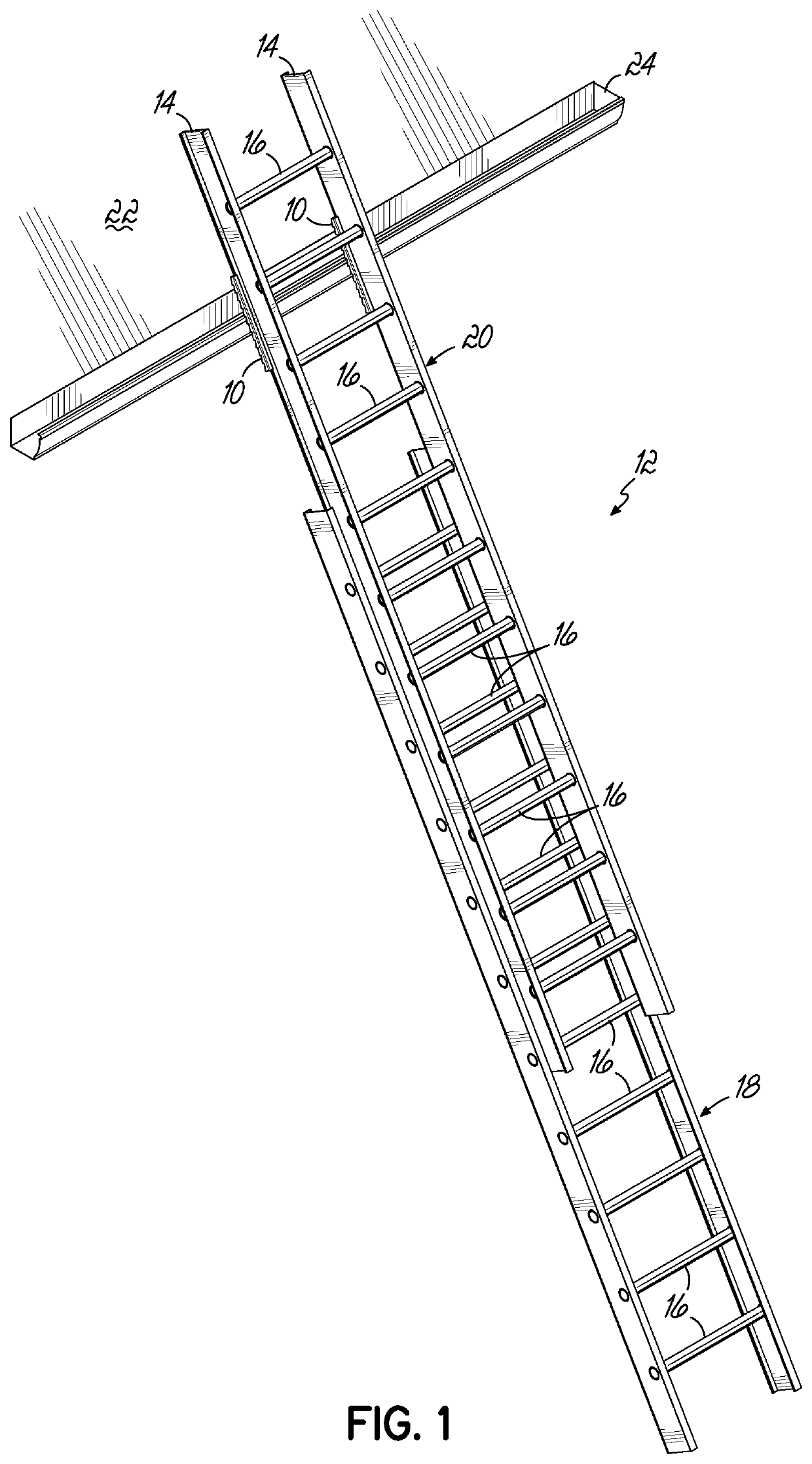
[0019]FIG. 1 shows a pair of ladder stabilizers 10 in use, according to a preferred embodiment of the invention. More particularly, the ladder stabilizers 10 are mounted to a ladder 12 that includes a pair of spaced rails, or legs, 14, and a plurality of steps, or rungs, 16, that span and connect the rails 14. The ladder 12 in FIG. 1 is an extension ladder 12, and it includes a base section 18 and a fly, or extension, section 20. Nonetheless, the present invention is equally applicable to ladders that are not extension ladders. Further, in FIG. 1 the ladder leans against, or engages, a structure 22, which in this case is a gutter 24.

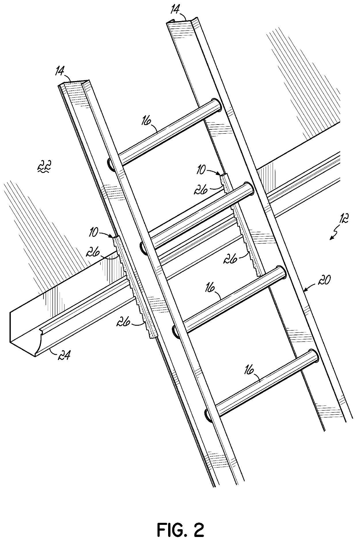
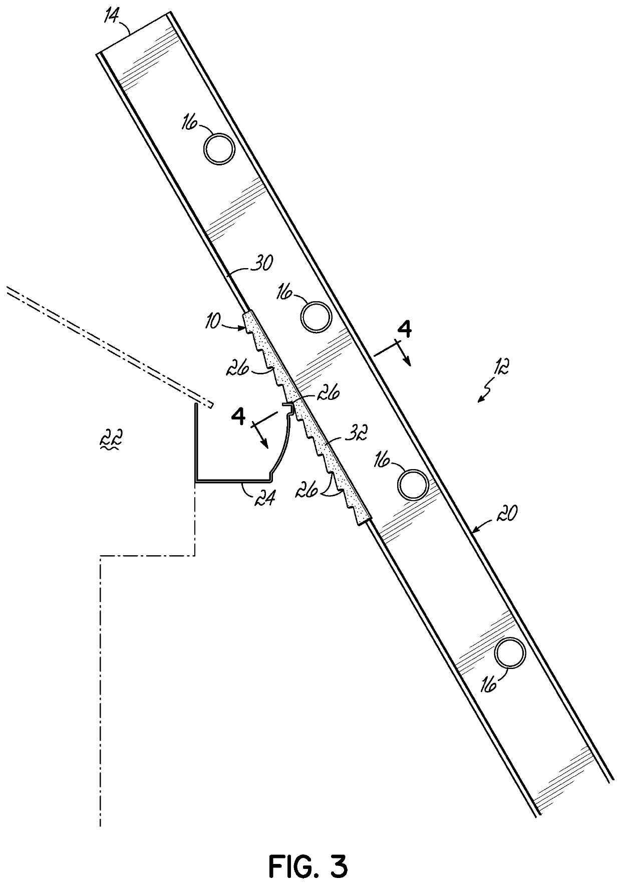
[0020]FIG. 2, an enlarged view, shows the two stabilizers 10 in more detail, with each one being an elongated, or longitudinal member, and having a plurality of steps, or step-like serrations 26, along a first longitudinal external surface thereof. The side view of FIG. 3 more clearly shows the steps 26 of the stabilizer 10 relative to the gutter 24. The...


PUM


Abstract

A ladder stabilizer removably mounts to one of the two spaced rails of a conventional ladder, and a mirror image stabilizer preferably mounts to the other rail. The stabilizer is of unitary construction, preferably injection molded from thermoplastic material, and includes a longitudinal member with an open channel along one longitudinal surface, the channel bounded by opposing longitudinal flanges. The member is sized and shaped and of sufficient flexibility to removably mount to the rail at any desired vertical position, and is relatively non-slidable with respect thereto once mounted. An opposite longitudinal surface of the member includes a plurality of step-like serrations. With one stabilizer mounted to each of the two ladder rails, and the ladder leaned against a structure for conventional use, the step-like serrations reduce the risk of movement of the ladder relative to the structure, and therefore promote safe use of the ladder. Also, the composition of the stabilizer protects the structure from any adverse effects.

Description

RELATED APPLICATION[0001]This application claims priority to U.S. Provisional Patent Application Ser. No. 63 / 123,654, entitled “Ladder Gutter & Architectural Protective Device,” and filed on Dec. 10, 2020, and also to U.S. Design patent application Ser. No. 29 / 817,234 entitled “Ladder Stabilizer,” and filed on Nov. 30, 2021, each of which is expressly incorporated herein, in its entirety.FIELD OF THE INVENTION[0002]The present invention relates to a device that stabilizes a conventional ladder when in use, while also protecting the corresponding structure that supports the ladderBACKGROUND OF THE INVENTION[0003]Ladders are well known, and regularly used to enable a person to increase his or her vertical reach or vertical level. Typically, the user leans the two spaced side rails of the ladder against a structure, often a building, for example the gutter of a building, then checks to make sure that the ladder is stable, and then proceeds up the steps, or rungs of the ladder, as neede...

Claims


Application Information

Patent Timeline
Patent Type & Authority Applications(United States)
IPC IPC(8): E06C7/48E06C7/06
CPCE06C7/486E06C7/488E06C7/06E06C7/188
Inventor HARDOERFER, SCOTTVOLZ, THOMAS A.
Owner LADDER FROG LLC
Why Eureka
Try Eureka