Fluid connector having a deformable tab and plug/connector assembly

a technology of connectors and tabs, applied in the direction of pipe couplings, couplings, instruments, etc., can solve the problems of reducing affecting the service life of the connector, so as to reduce the leakage path, the connection is robust, and the connection is robust

Active Publication Date: 2020-11-03
OTIKER NJ INK
View PDF19 Cites 3 Cited by
  • Summary
  • Abstract
  • Description
  • Claims
  • Application Information

AI Technical Summary

Benefits of technology

[0011]A primary object of the invention is to provide a fluid connector which can be secured to a plastic sealing hub and provide a robust connection between a tubular connector and a plastic component. A secondary object of the invention is to provide a fluid connector which can be secured to a sealing hub and provide a robust connection between a tubular connector and a fluid transfer component. Additionally, an object of the present invention is to reduce the leak paths between the tubular connector and the component and to allow for ease of shipping the connector with a sealing member secured to a removable plug in order to prevent contamination of the sealing member until assembly is completed.

Problems solved by technology

This fixed, rigid configuration causes complications during operation due to vibrations from the engine transmitted to components located in the engine bay.
If a fluid hose is vibrated in excess, this can place excessive stress and strain on the connection between the fluid connector and the fluid hose, causing the connection to become weak.
Additionally, the connection between the fluid connector and fluid hose may leak fluid due to an improper fit which, in turn, could cause excessive fluid loss in critical components such as the engine, causing overheating and possible damage if not discovered and fixed.
Additionally, as the size and weight of automobiles shrink, so do the components within the vehicle.
Unfortunately, plastic is not as robust as metal and is prone to failure around sealing hubs due to stress concentrations and strength of the plastic itself.
Moreover, similar problems exist for automobile components made of materials other than plastic that are more lightweight than metal.

Method used


Image

  • Fluid connector having a deformable tab and plug/connector assembly
  • Fluid connector having a deformable tab and plug/connector assembly
  • Fluid connector having a deformable tab and plug/connector assembly

Examples


first embodiment

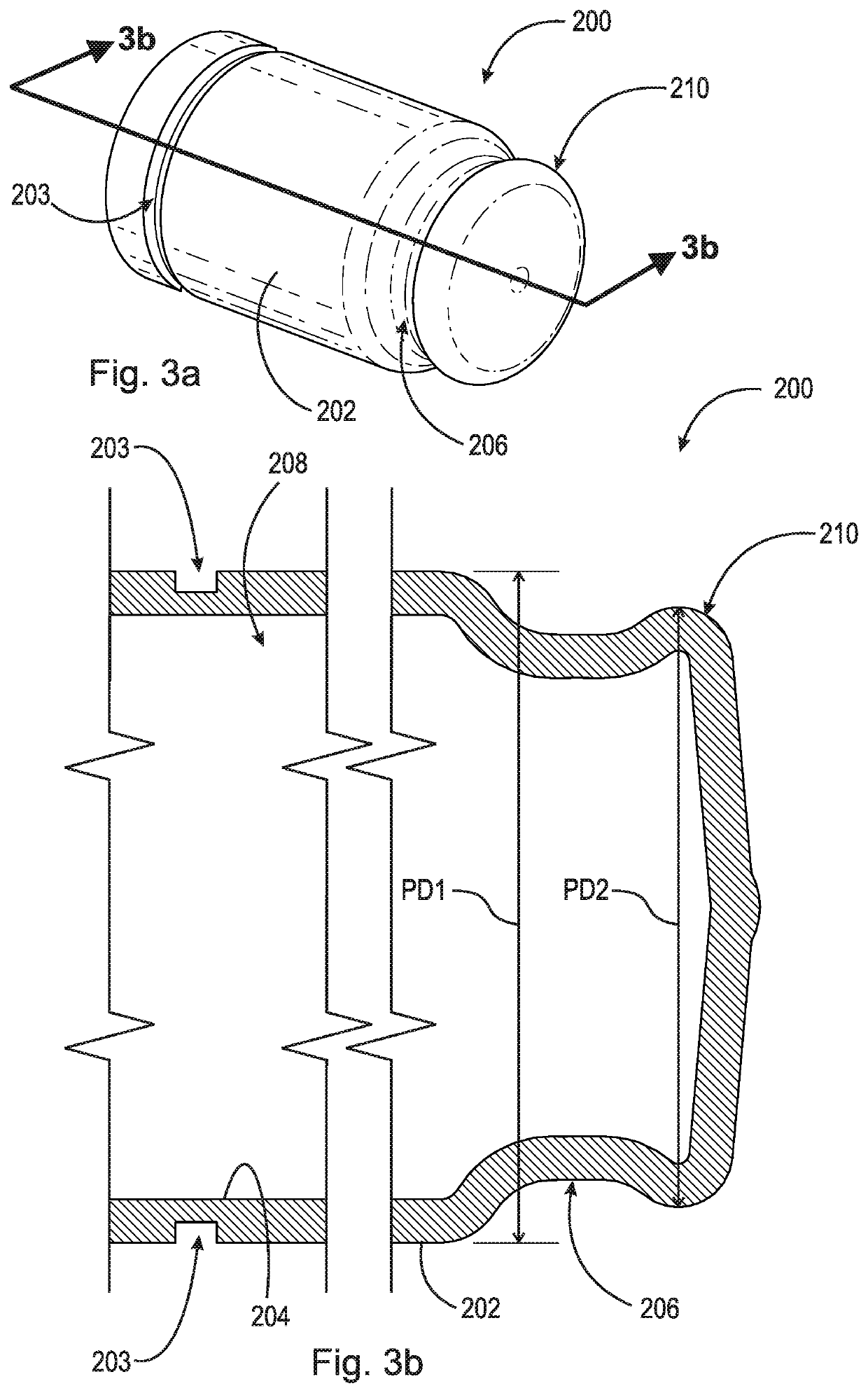
[0038]FIG. 3a and FIG. 3b are a perspective view and a cross-sectional view, respectively, of plug 200. Plug 200 includes outer surface 202, inner surface 204, indent 206, cavity 208, and tab 210. Indent 206 is a circumferentially arranged groove on plug 200 which allows plug 200 to secure a sealing member 330 to outer surface 202 (shown in FIG. 6). Plug 200 has a diameter PD1 and a diameter PD2 where diameter PD1 is larger than diameter PD2. In a preferred embodiment, plug 200 is manufactured from a deformable material such as rubber or plastic. Additionally, plug 200 could be manufactured in order to seal through-bore 112 of fluid connector 100 in order to pressure test a device which fluid connector 100 is secured to. A preferred embodiment including a sealing feature for plug 200 is groove 203. Groove 203 is circumferentially arranged on outer surface 202. Snap ring 120 (shown in FIG. 7) would engage groove 203 and prevent plug 200 from being forced out of fluid connector 100. I...

second embodiment

[0039]FIG. 3c and FIG. 3d are a perspective view and a cross-sectional view, respectively, of plug 230. Plug 230 includes outer surface 232, inner surface 234, indent 236, cavity 238, tab 240, and channel 242. Indent 236 is a circumferentially arranged groove on plug 230 which allows plug 230 to secure a sealing member 330 to outer surface 232 (shown in FIG. 6). Tab 240 and channel 242 are circumferentially arranged on plug 230. Channel 242 is a continuous groove that extends axially into plug 230. Plug 230 has a diameter PD1 and a diameter PD3 where diameter PD1 is smaller than diameter PD3. When plug 230 is removed from fluid connector 100 (shown in FIG. 1), channel 242 allows tab 240 to deform around a sealing member 330 (shown in FIG. 6). In a preferred embodiment, plug 230 is manufactured from a deformable material such as rubber or plastic. Additionally, plug 230 could be manufactured in order to seal through-bore 112 of fluid connector 100 in order to pressure test a device w...

third embodiment

[0040]FIG. 3e and FIG. 3f are a perspective view and a cross-sectional view, respectively, of plug 260. Plug 260 includes outer surface 262, inner surface 264, indent 266, cavity 268, and tab 270. Indent 266 is a circumferentially arranged groove on plug 260 which allows plug 260 to secure a sealing member 330 to outer surface 262 (shown in FIG. 6). Tab 270 is circumferentially arranged on plug 260. In a preferred embodiment, plug 260 is manufactured from a deformable material such as rubber or plastic. Additionally, plug 260 could be manufactured in order to seal through-bore 112 of fluid connector 100 in order to pressure test a device which fluid connector 100 is secured to. It should be appreciated, however, that the use of a either plug 200, 230, or 260 in combination with either groove 203 or channels 243 can be used to seal fluid connector 100 for pressure testing and alignment of sealing member 330 within fluid connector 100 and hub 300.

[0041]FIG. 4 is a perspective view of ...


PUM

PropertyMeasurementUnit
diameteraaaaaaaaaa
pressureaaaaaaaaaa
temperatureaaaaaaaaaa

Abstract

A fluid connector comprising a body having a through-bore, a plurality of radially inwardly facing surfaces comprising a first cylindrical surface having a first diameter, a frusto-conical surface adjacent the first cylindrical surface, and a second cylindrical surface adjacent the frusto-conical surface, the second cylindrical surface having a second diameter, wherein the frusto-conical surface is arranged between the first and second cylindrical surfaces, and a plurality of outwardly facing surfaces comprising a first cylindrical surface having a first diameter, and a second cylindrical surface adjacent the first cylindrical surface, the second cylindrical surface having a second diameter, and a deformable tab integrally connected to the body and extending axially from the body.

Description

CROSS-REFERENCE TO RELATED APPLICATIONS[0001]This application claims the benefit under 35 U.S.C. § 119(e) of U.S. Provisional Application No. 62 / 303,137, filed Mar. 3, 2016, which application is incorporated herein by reference in its entirety.FIELD OF THE INVENTION[0002]The invention relates generally to a fluid connector, and, more specifically, to a fluid connector with a deformable tab adapted to be crimp-connected to an output port of a fluid receiving device in such a way as to reduce possible leak paths in the fluid circuit. The invention also relates to an assembly of the fluid connector and a plug, arranged to permit shipment of the connector with a seal.BACKGROUND OF THE INVENTION[0003]Fluid connectors are integral components for many applications, and especially for automotive applications. Since an automotive system is made up of various components such as a radiator, transmission, and engine, fluid must be able to travel not only within each component but also between c...

Claims


Application Information

Patent Timeline
Patent Type & Authority Patents(United States)
IPC IPC(8): F16L55/11F16L13/16F16L37/088F16L27/08B60K1/00G01L19/00F16L37/38
CPCG01L19/0007F16L55/11F16L27/0845F16L13/163F16L55/1141F16L37/0885B60K1/00F16L37/38F16L2201/30
Inventor FREMONT, BRADLEY C.ZILLIG, STEVEN R.
Owner OTIKER NJ INK
Why Eureka
Try Eureka