Catheter having a multilayered shaft section with a reinforcing mandrel

a multi-layered, reinforcing mandrel technology, applied in the field of catheters, can solve the problems of ineffective transmission of axial force by the support mandrel, various drawbacks in the prior art design, etc., and achieve the effects of improving kink resistance, excellent trackability, and convenient advancemen

Inactive Publication Date: 2005-01-04
ABBOTT CARDIOVASCULAR
View PDF39 Cites 58 Cited by
  • Summary
  • Abstract
  • Description
  • Claims
  • Application Information

AI Technical Summary

Benefits of technology

The catheter of the invention is highly pushable, flexible, trackable and kink resistant due to the reinforcing mandrel secured between the first and second layers of the shaft. The shaft of the invention provides an improved transition between the proximal shaft section and the more flexible distal shaft section, for improved kink resistance. Thus, t...

Problems solved by technology

Despite these attempts, prior art designs have suffered from various drawba...

Method used


Image

  • Catheter having a multilayered shaft section with a reinforcing mandrel
  • Catheter having a multilayered shaft section with a reinforcing mandrel
  • Catheter having a multilayered shaft section with a reinforcing mandrel

Examples


Embodiment Construction

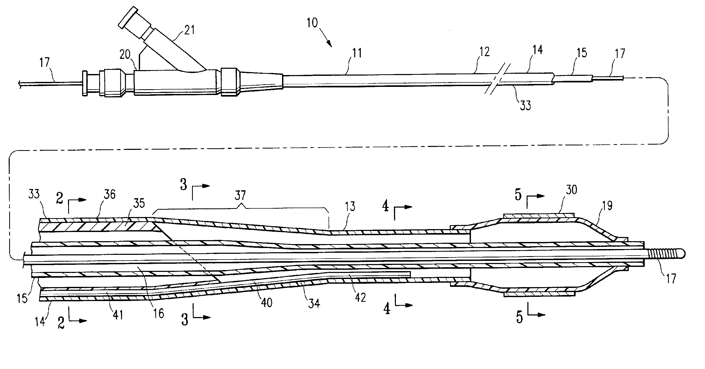
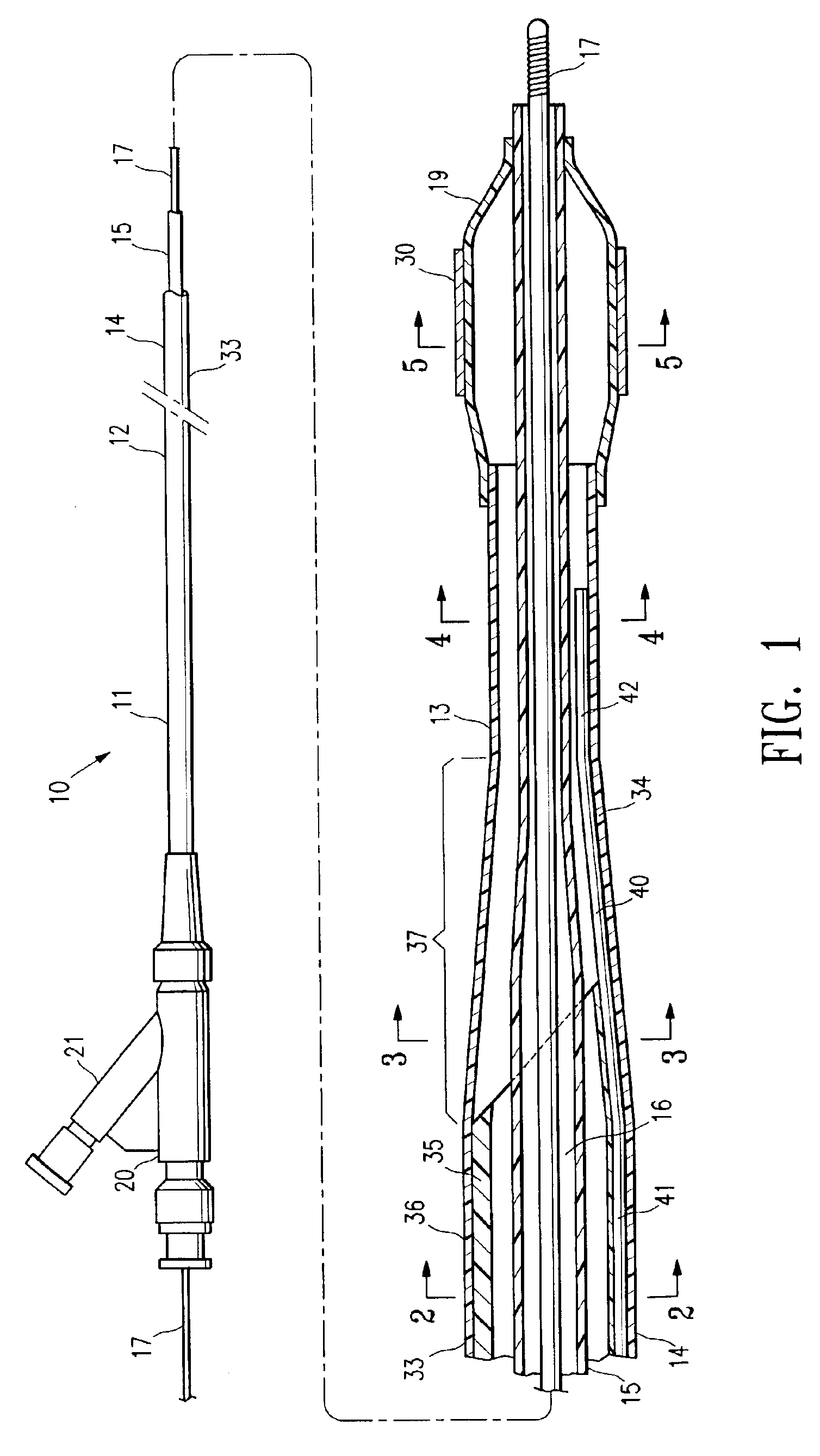
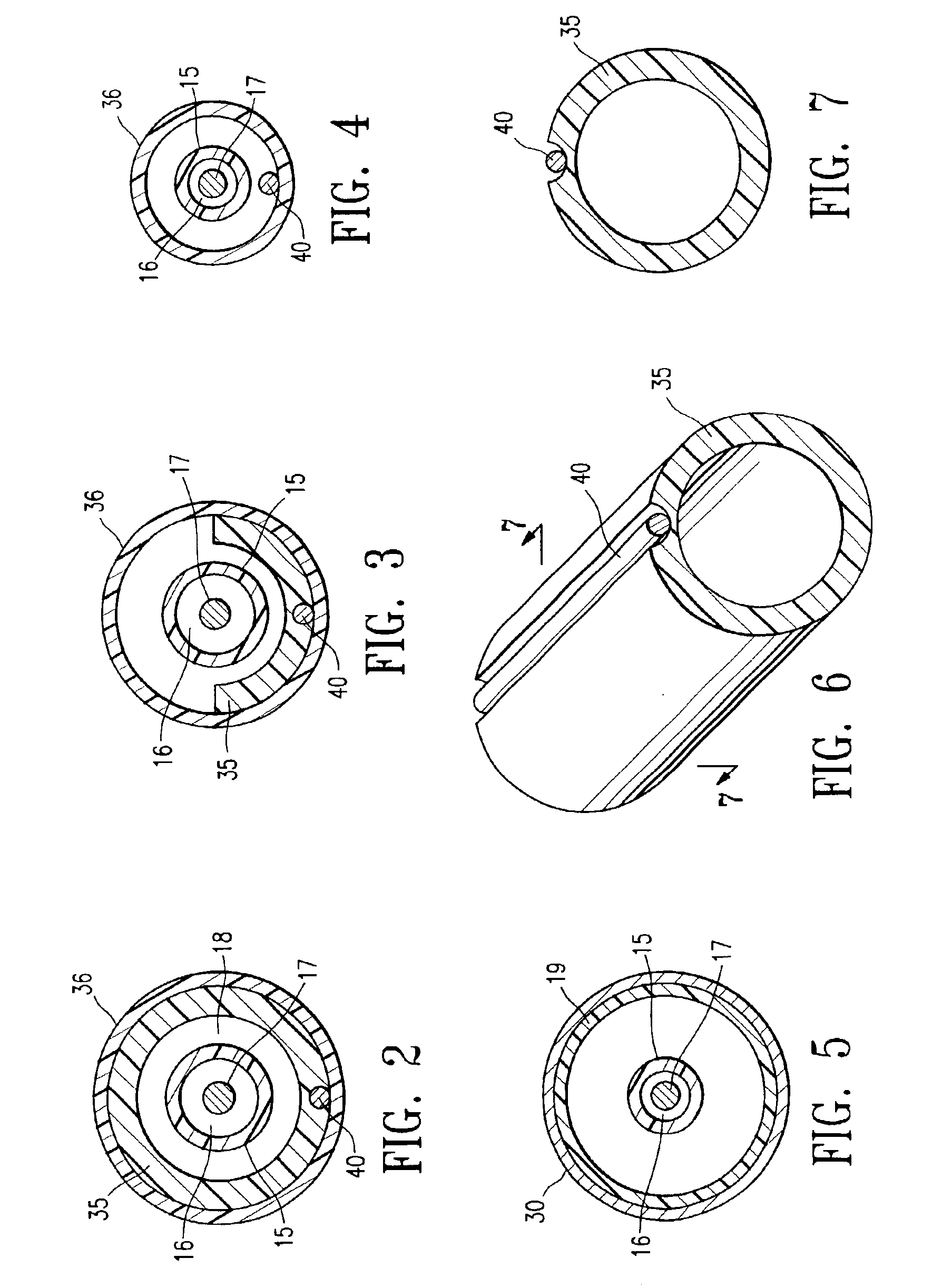
FIG. 1 illustrates an over-the-wire balloon catheter 10 embodying features of the invention. Catheter 10 generally comprises an elongated catheter shaft 11 having a proximal end, a distal end, a proximal shaft section 12, a distal shaft section 13, an outer tubular member 14, and an inner tubular member 15. Inner tubular member 15 defines a guidewire lumen 16 adapted to slidingly receive a guidewire 17. The coaxial relationship between outer tubular member 14 and inner tubular member 15 defines annular inflation lumen 18, as best shown in FIGS. 2-4, illustrating transverse cross sections of the catheter of FIG. 1, taken along lines 2—2, 3—3 and 4—4, respectively. An inflatable balloon 19 is disposed on the distal shaft section 13, having a proximal skirt section sealingly secured to the distal end of outer tubular member 14, and a distal skirt section sealingly secured to the distal end of inner tubular member 15, so that its interior is in fluid communication with inflation lumen 1...


PUM

PropertyMeasurementUnit
Fractionaaaaaaaaaa
Lengthaaaaaaaaaa
Diameteraaaaaaaaaa

Abstract

A catheter having an elongated shaft having at least a section which is multilayered with a first layer and a second layer secured to the first layer, and a mandrel having at least a section between the first and second layers. In one presently preferred embodiment, the mandrel is in contact with an outer surface of the first layer and with an inner surface of the second layer.

Description

BACKGROUND OF THE INVENTIONThis invention generally relates to catheters, and particularly intravascular catheters for use in percutaneous transluminal coronary angioplasty (PTCA) or for the delivery of stents.In percutaneous transluminal coronary angioplasty (PTCA) procedures a guiding catheter is advanced in the patient's vasculature until the distal tip of the guiding catheter is seated in the ostium of a desired coronary artery. A guidewire is first advanced out of the distal end of the guiding catheter into the patient's coronary artery until the distal end of the guidewire crosses a lesion to be dilated. A dilatation catheter, having an inflatable balloon on the distal portion thereof, is advanced into the patient's coronary anatomy over the previously introduced guidewire until the balloon of the dilatation catheter is properly positioned across the lesion. Once properly positioned, the dilatation balloon is inflated with inflation fluid one or more times to a predetermined s...

Claims


Application Information

Patent Timeline
IPC IPC(8): A61M25/00A61M25/10A61F2/958
CPCA61M25/005A61M25/0053Y10T428/13A61M2025/0063A61M2025/1086A61M25/10
Inventor DUCHAMP, JACKY G.
Owner ABBOTT CARDIOVASCULAR
Why Eureka
Try Eureka