Multipolar magnetogenerator

a magnetogenerator and multi-polar technology, applied in the direction of synchronous generators with multiple outputs, magnetic circuit shapes/forms/construction, windings, etc., can solve the problems of not reaching the total output of generated power, nevertheless generating relatively large energy, etc., and achieve excellent spatial efficiency and sufficient performance.

Inactive Publication Date: 2005-01-18
HONDA MOTOR CO LTD
View PDF7 Cites 9 Cited by
  • Summary
  • Abstract
  • Description
  • Claims
  • Application Information

AI Technical Summary

Benefits of technology

to provide a multipolar magnetogenerator operable under sufficient performance of its capability of power generation, nevertheless permitting simultaneous extraction of various voltage outputs, and excellent in spatial efficiency.

Problems solved by technology

Multipolar magnetogenerators are compact and light but can nevertheless generate relatively large energy.
Although the conventional multipolar magnetogenerator is available for high-output drive, since it uses salient poles independently in a role-sharing manner as power generating portions different in output characteristics, its total output of generated power does not reach the output that should be obtained when making the best use of the true capability of power generation.

Method used


Image

  • Multipolar magnetogenerator
  • Multipolar magnetogenerator
  • Multipolar magnetogenerator

Examples


Embodiment Construction

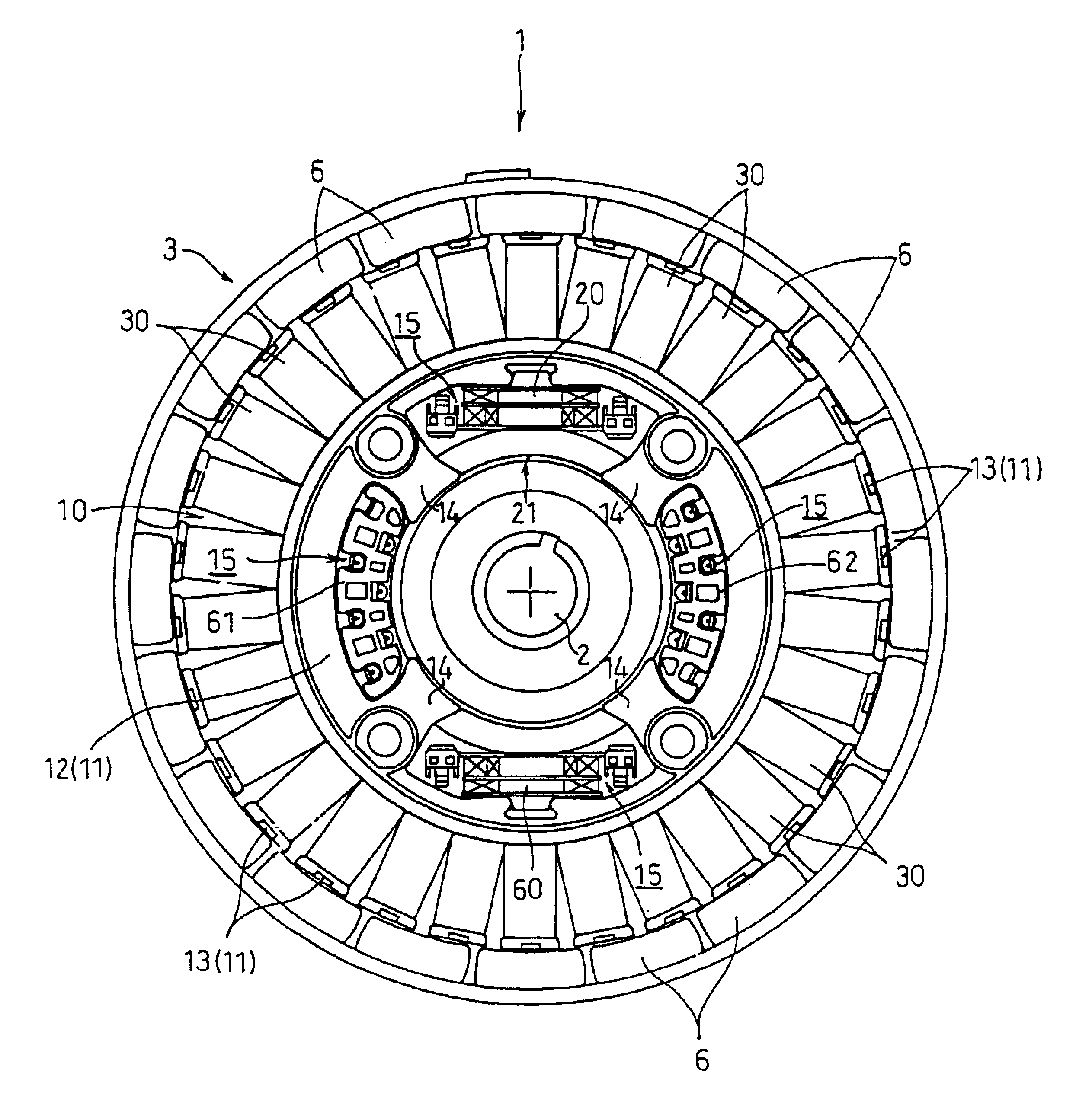
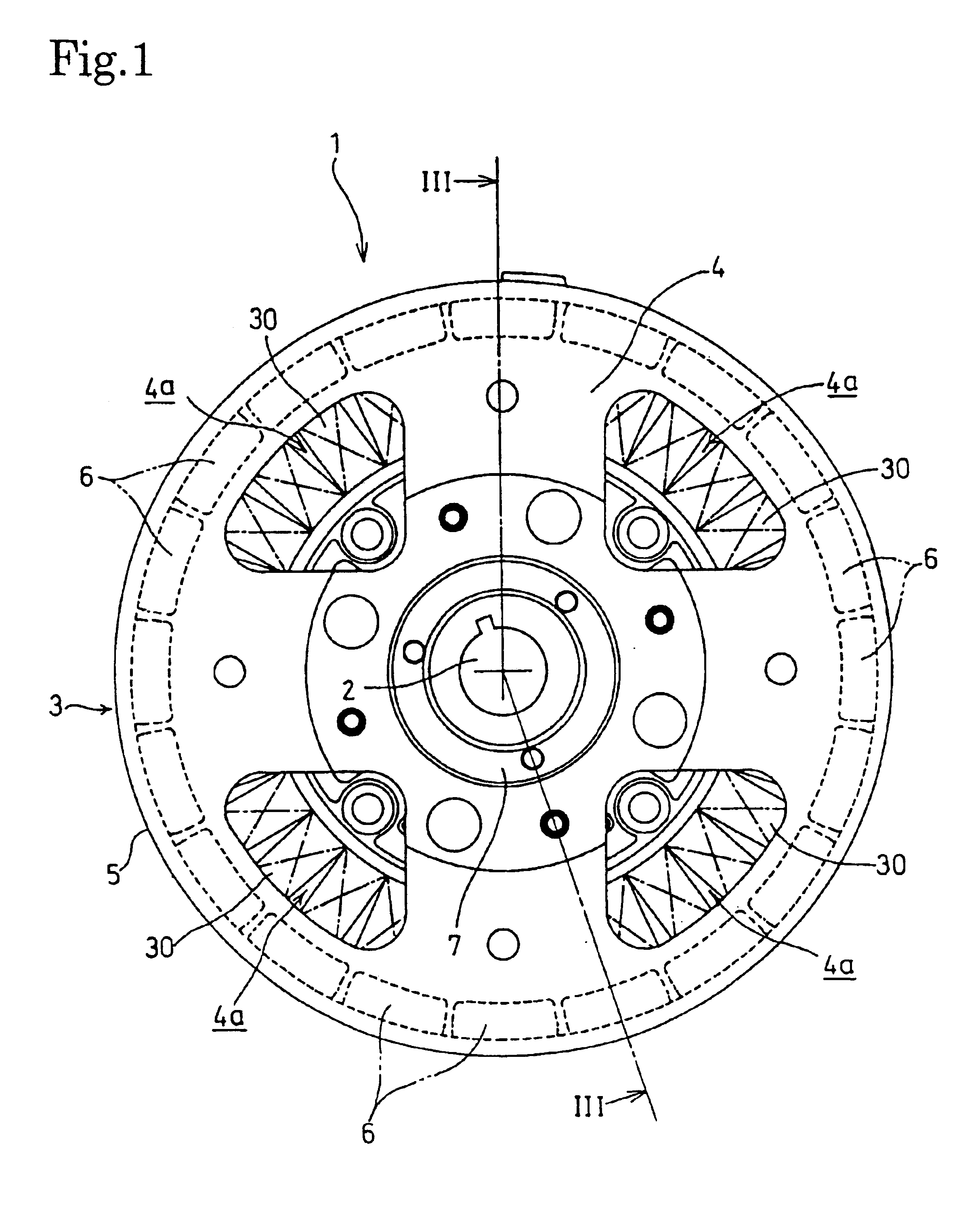
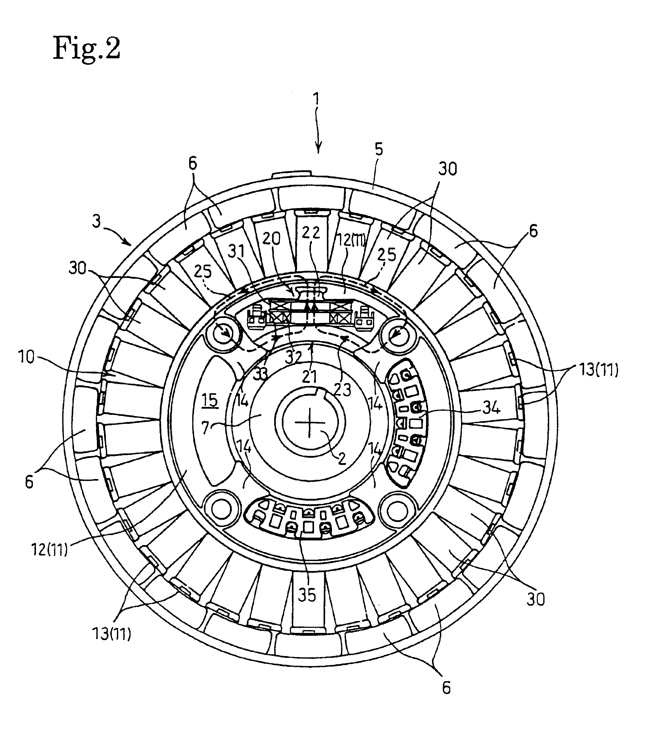
An embodiment of the invention will now be described below with reference to FIGS. 1 through 6. A multipolar magnetogenerator according to the embodiment is shown in its front elevational view in FIG. 1 and in its back view in FIG. 2. In addition, a sectional view taken along the line III—III of FIG. 1 is shown in FIG. 3. The multipolar magnetogenerator according to the invention is of an outer rotor type placing an annular magnet rotor 3 around a stator 10 (FIG. 2).

The magnet rotor 3 constitutes an outer rotor commonly used as a flywheel. As best shown in FIG. 3, the magnet rotor 3 has a disk-shaped bottom wall 4 and a cylindrical outer wall 5 that form a bottomed cylinder or a cup. The magnet rotor 3 is fitted on a rotary shaft 2 extending through the bottom wall 4 via a sleeve 7, and supported by the rotary shaft 2 to rotate together with the rotary shaft 2. The bottom wall 4 of the cylindrical magnet rotor 3 has a circular bore receiving the central sleeve 7 therein, and has for...


PUM


Abstract

A multipolar magnetogenerator, which is operable under sufficient performance of its capability, permitting simultaneous extraction of various voltage outputs and is excellent in spatial efficiency, includes a magnet rotor (3) as an outer rotor and a multipolar stator (10) opposed to the radially inner surface of the magnet rotor (3) to permit extraction of an output of generated power from output windings (30) wound around the stator core 10. A transformer core (21) has a primary winding (31) and secondary windings (32, 33) wound therearound and is located adjacent the radially inner circumferential surface of the stator (10), which is remote from the magnet rotor (3), and the output windings (30) are connected to the primary wiring (32) such that transformed outputs are extracted from the secondary windings (32, 33).

Description

BACKGROUND OF THE INVENTION1. Field of the InventionThis invention relates to a multipolar magnetogenerator having a magnetic rotor and an opposed multipolar stator to permit extraction of generated power from output windings wrapping the stator core.2. Description of the Related ArtMultipolar magnetogenerators are compact and light but can nevertheless generate relatively large energy. Recently, therefore, they are widely used as power sources of engine-driven portable generators, such as power-generating portions of inverter-controlled generators.In case of extracting different independent outputs, like different voltage outputs, from such a multipolar magnetogenerator, it was a typical way to wrap multiple generating portions of the stator with windings adjusted for required outputs independently as disclosed in Japanese Examined Utility Model Publication hei 7-13405.FIG. 9 shows the stator 01 of an outer rotor type generator that is the multipolar magnetogenerator disclosed by t...

Claims


Application Information

Patent Timeline
Patent Type & Authority Patents(United States)
IPC IPC(8): H02K21/22H02K21/48H02K21/00H02K1/00H02K19/34
CPCH02K21/48H02K21/22
Inventor HIRANO, TSUTOMUSHINKAWA, YASUHIRO
Owner HONDA MOTOR CO LTD
Why Eureka
Try Eureka