Very thin fan motor with attached heat sink

a fan motor and heat sink technology, applied in the direction of piston pumps, magnetic circuit rotating parts, magnetic circuit shapes/forms/construction, etc., can solve the problems of increasing the volume of heat per unit time, increasing the heat density of electronic circuits and internal elements such as semiconductors, and further downsizing this portable equipment. , to achieve the effect of stable processing speed, high performance and rapid improvement performan

Inactive Publication Date: 2005-03-29
NAMIKI PRECISION JEWEL CO LTD
View PDF3 Cites 43 Cited by
  • Summary
  • Abstract
  • Description
  • Claims
  • Application Information

AI Technical Summary

Benefits of technology

In this situation, the very thin fan motor with heat sink attached has attracted attention as a cooling means to deal with heat in equipment with CPUs with rapidly improving performance. The cooling means will make it possible to use the next era of GHz-class CPUs in high-performance personal computers that can assure stable processing speeds with extremely high performance.
This invention provides a very thin fan motor with heat sink attached that has excellent heat-radiation cooling efficiency and adequate performance even in a very thin, flat fan motor with external measurements about 30 mm square and 3 mm thick. Structurally, the fan motor has a small number of parts, is light and thin, and can be assembled easily by an automatic assembler. Because of unit construction with inexpensive parts, the fan motor can be mass produced. It resolves the heat production problem of electronic parts described above, and so the invention provides a very thin fan motor with heat sink attached that can be applied in a wide range of fields, including office automation and factory automation equipment as well as mobile and portable terminals such as high-performance notebook personal computers.
The very thin fan motor with heat sink attached of this invention is a flat fan mounted in various kinds of electronic equipment that need to radiate heat, and particularly mounted directly on the CPU, characterized by having a fan motor mechanism that comprises a heat plate that supports a rotor fan that can rotate in a central position and that has a contact surface that matches the shape of the external surface of the item (such as a CPU) to be cooled, rotor magnets that are part of the rotor fan and are positioned around the periphery on the surface of the heat plate, and a stator coil substrate; by having multiple thin metal heat radiation fins with excellent thermal conductivity arranged in parallel at a fixed interval above the heat plate outside the rotor fan as cooling heat-radiation fins; and by combining the function of cooling heat sink with the heat radiation fins that conduct the heat absorbed from the heat plate and radiate it away by the action of the air moved by the rotor fan.

Problems solved by technology

However, the biggest obstacle to further downsizing of this portable equipment is the increased heat density of electronic circuits and internal elements such as semiconductors.
That is, the increased volume of heat per unit-time, or heat wattage, within the equipment constitutes a major, urgent problem to be resolved in order for higher performance CPU integrated circuits to continue to perform vigorous operations.
All of these have provided some degree of cooling capacity, but their size has not been as small as desired.
They have not been of a size suited to portable electronic equipment with the smallness, lightness and portability required of the very thin, notebook-sized personal computers of recent years.
This is excellent from the perspective of efficient cooling of the PC as a whole, but it is of course not a structure that can cope with slimmed down equipment.
Because the light and slim bodies of the latest notebook personal computers do not have installation space, particularly in the direction of the thickness of the case, countermeasures against heat are an important problem in terms of taking advantage of the capabilities of high-performance CPUs.
. . and the air does not exit smoothly.
Therefore, the available cooling effect is not as great as expected.
. . and the air does not exit smoothly.

Method used


Image

  • Very thin fan motor with attached heat sink
  • Very thin fan motor with attached heat sink
  • Very thin fan motor with attached heat sink

Examples


Embodiment Construction

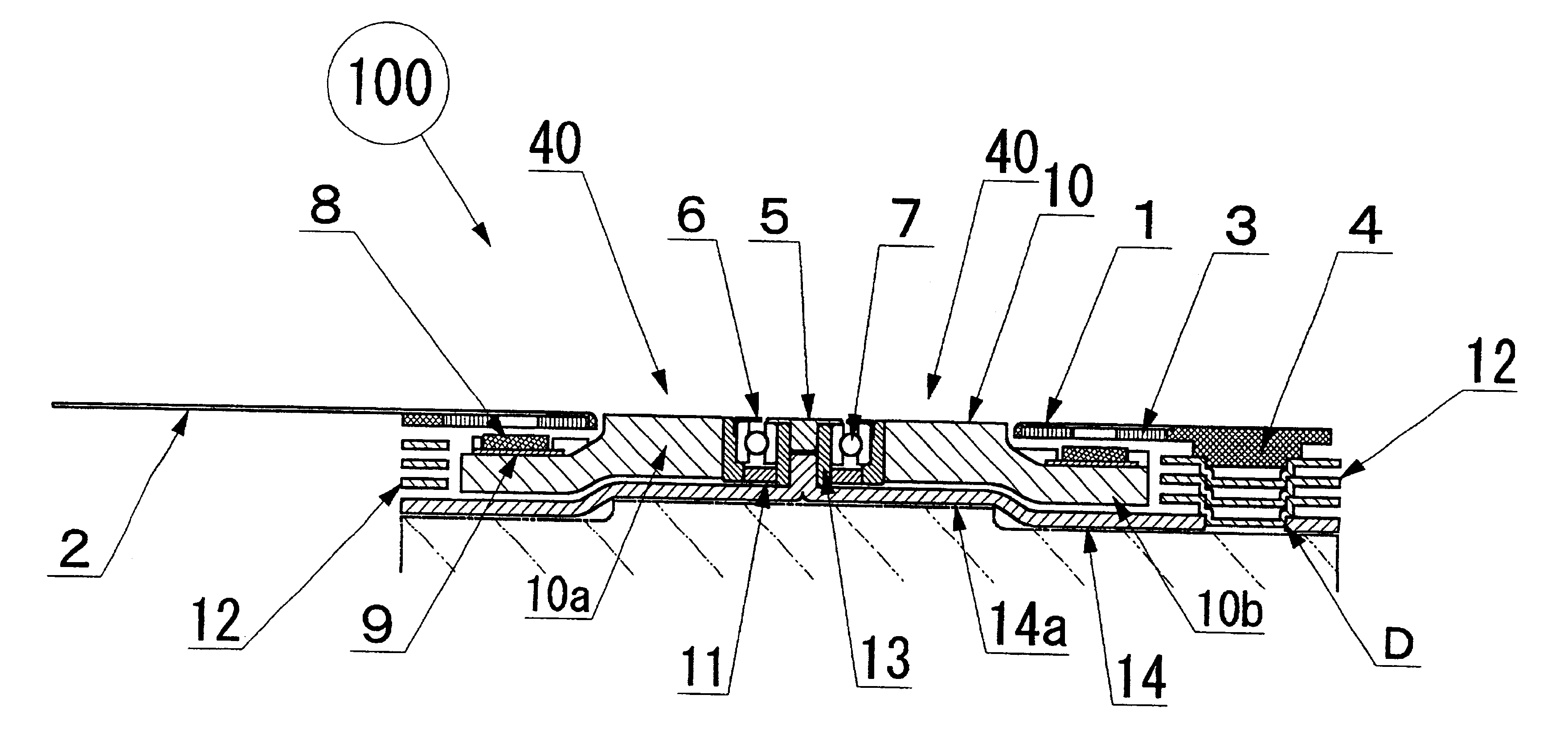
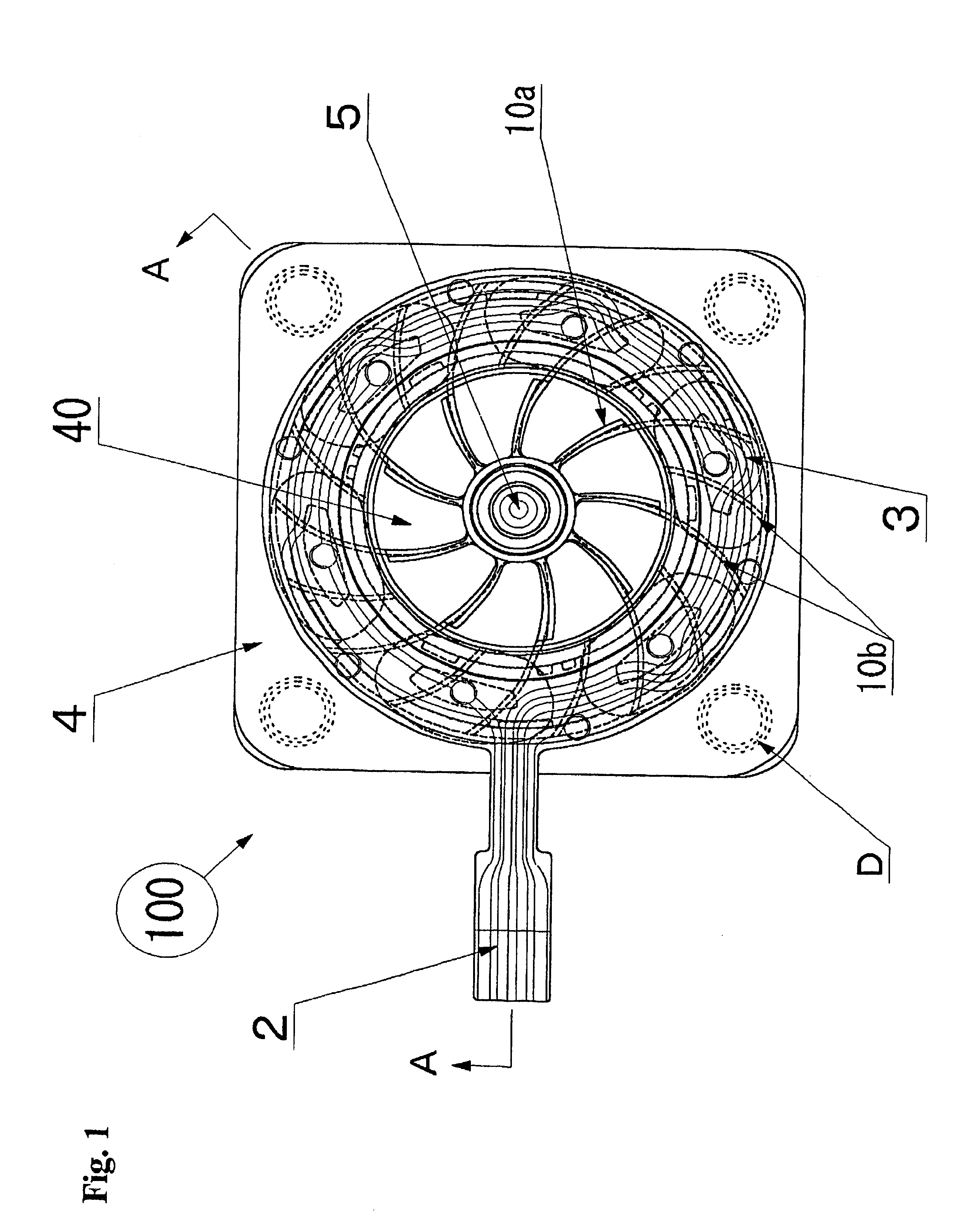
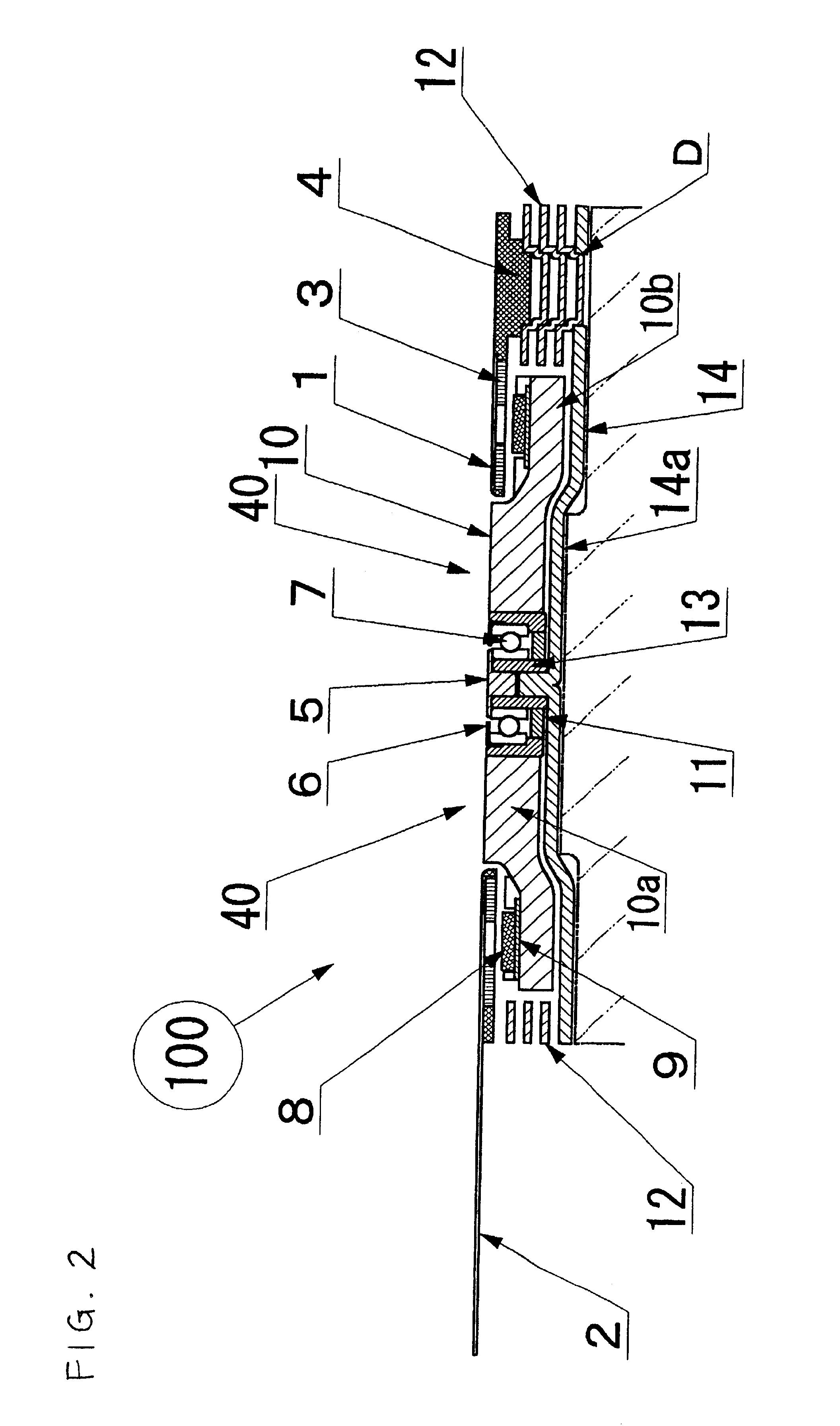
The very thin fan motor with heat sink attached 100 of this invention is explained below with reference to FIGS. 1 through 4. FIG. 1 (which differs from the actual outward appearance in order to explain the internal structure) and figure are a conceptual plane view and cross section showing the structure of the thin fan motor. FIG. 3 is an exploded oblique view showing the constitution of parts of the fan motor as a whole, and FIG. 4 is a conceptual plane view showing the flat motor fan with rotating blades that incorporate magnets.

The basic structure of the very thin fan motor 100 of this invention is shown in FIGS. 1 through 3. It comprises three major units; these are the heat sink unit for cooling by radiation of heat, that has a metal heat plate 14 mounted directly on the CPU and heat radiation fins 12 held together by connectors D, a rotor fan 10 unit in which a shaft 13 is supported and the rotor fan 10 is free to turn on ball bearings 7 in the center of the heat plate 14, an...


PUM


Abstract

A very thin fan motor with an attached heat sink that has high heat radiation and air cooling effects in a small, flat, thin package, that has a simple and easily assembled overall structure as a fan motor, and that has superior cooling efficiency. A flat fan mounted in various kinds of electronic equipment that need to radiate heat, and particularly mounted directly on the CPU, characterized by having a fan motor mechanism that comprises a heat plate that supports a rotor fan that can rotate in a central position and that has a contact surface that matches the shape of the external surface of the item (such as a CPU) to be cooled, rotor magnets that are part of the rotor fan and are positioned around the periphery on the surface of the heat plate, and a stator coil substrate, by having multiple metal heat radiation fins with excellent thermal conductivity, which are thin heat-radiating fins, arranged in parallel at a fixed interval on the heat plate pointing outward from the rotor fan as cooling heat-radiation fins, and by combining the function of cooling heat sink with the heat radiation fins that conduct the heat absorbed from the heat plate and radiate it away by the action of the air moved by the rotor fan.

Description

BACKGROUND OF THE INVENTION1. Field of the InventionThis invention concerns cooling fan motors mounted in various kinds of electronic equipment that require heat radiation treatment, such as high performance CPU integrated circuits like microprocessors or IC circuit boards mounted in PCs (personal computers), and improvement of small, flat brushless motors suited to use in such cooling fan motors.2. Description of the Related ArtAs portable telephones, portable PCs and other kinds of electronic equipment have become smaller and more compact in recent years, various parts used within such equipment have necessarily become miniaturized. Electronics technology and semiconductor integration technology have undergone remarkable development in the fields of portable terminals for business mobile computing, desktop PCs, FAX machines, printers and other office automation equipment, drive and control devices for factory automation equipment including precision machining equipment and small i...

Claims


Application Information

Patent Timeline
Patent Type & Authority Patents(United States)
IPC IPC(8): H01L23/467H01L23/34H05K7/20H02K5/18H02K9/02H02K9/06H02K9/22
CPCH01L23/467H01L2924/0002H01L2924/00H02K9/02
Inventor ODAGIRI, KINYAOKI, KOUJISUZUKI, SHINGO
Owner NAMIKI PRECISION JEWEL CO LTD
Why Eureka
Try Eureka