Semiconductor device and method for manufacturing the same
a semiconductor and semiconductor technology, applied in the direction of polycrystalline material growth, crystal growth process, chemically reactive gas, etc., can solve the problem of limit on the transistor manufactured using an oxide semiconductor, and achieve the effect of high field-effect mobility
- Summary
- Abstract
- Description
- Claims
- Application Information
AI Technical Summary
Benefits of technology
Problems solved by technology
Method used
Image
Examples
embodiment 1
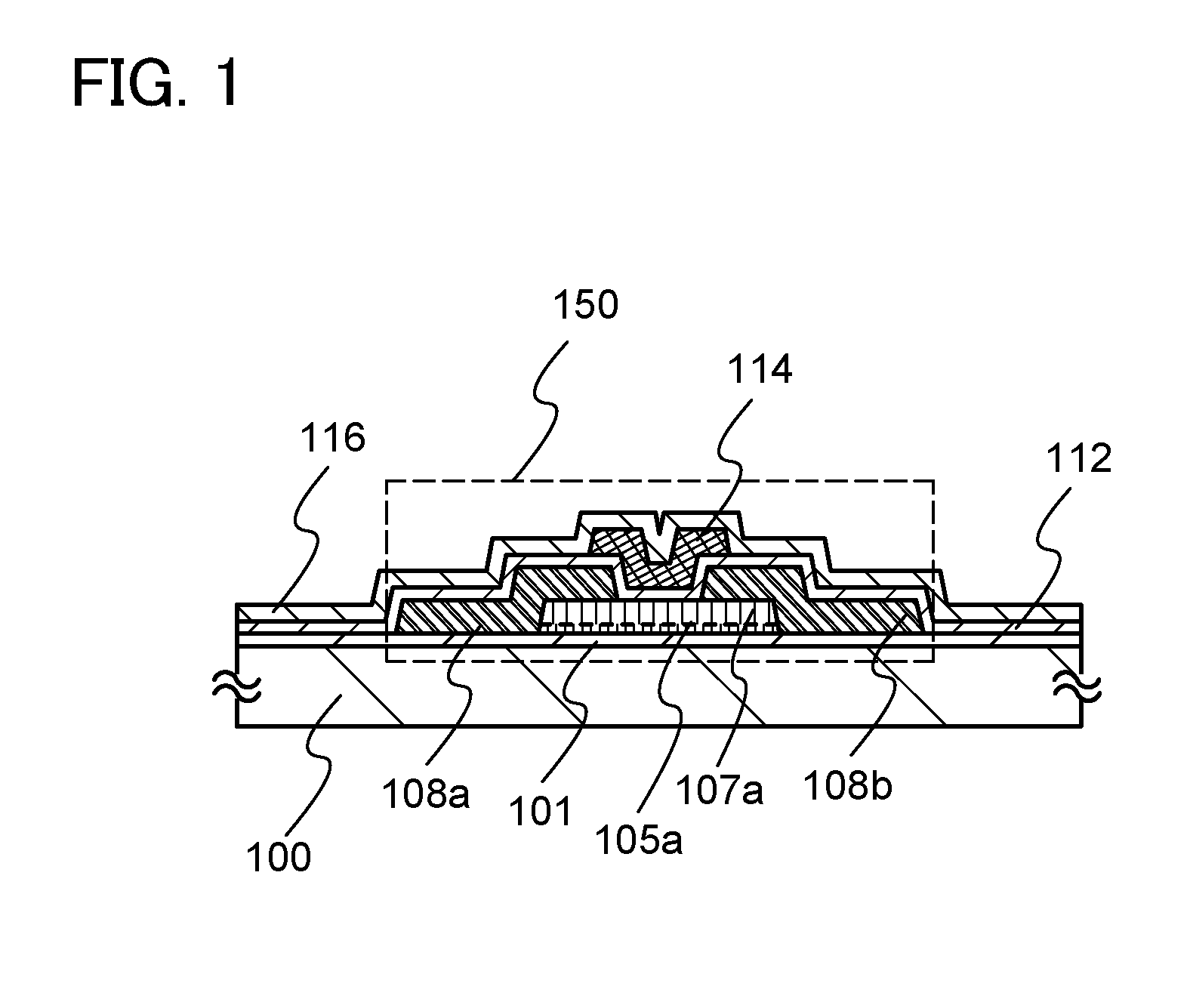
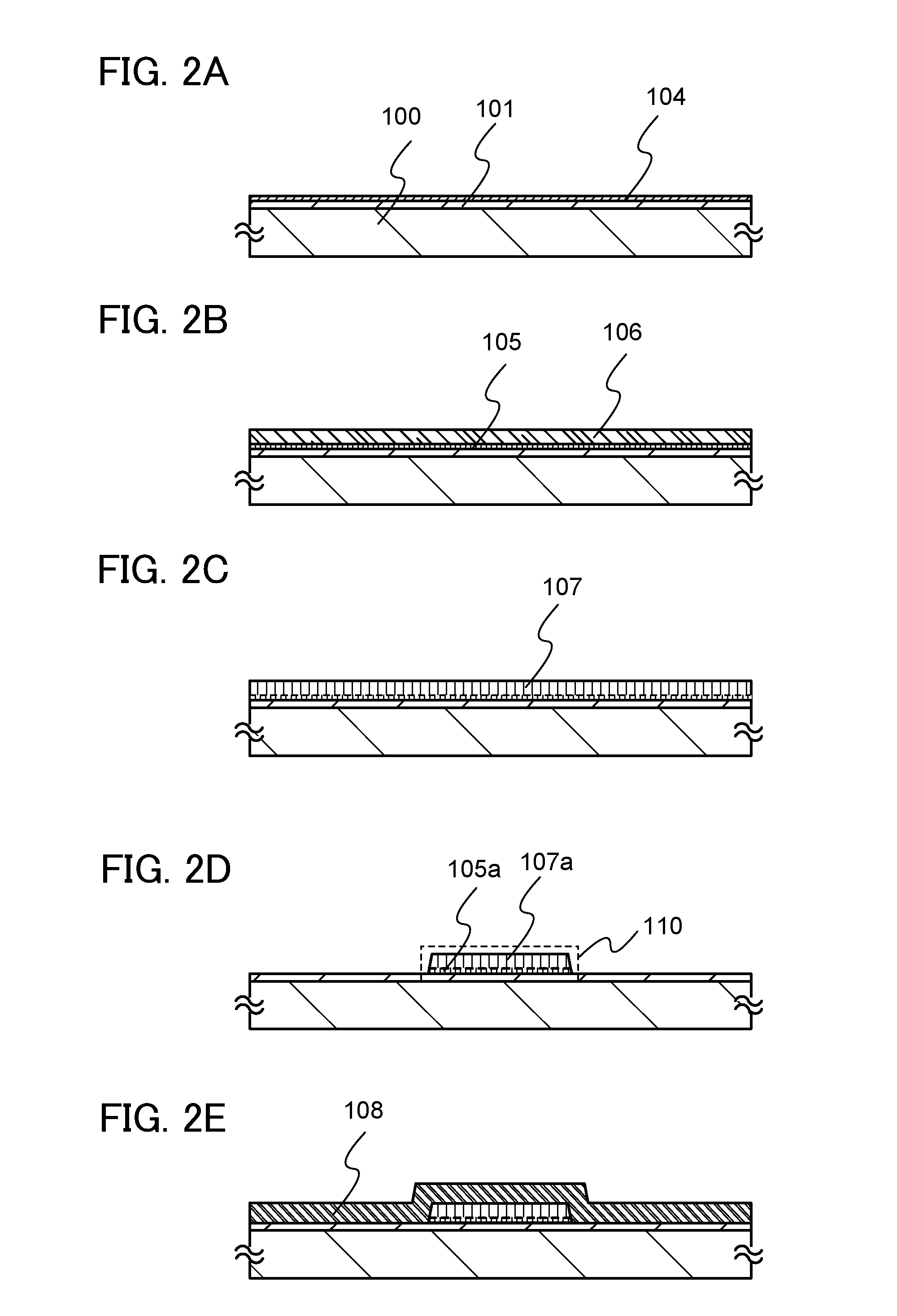
[0054]In this embodiment, a structure and a manufacturing method of a semiconductor device according to an embodiment of the invention disclosed herein will be described with reference to FIG. 1, FIGS. 2A to 2E, FIGS. 3A to 3D, FIG. 4, FIGS. 5A to 5C, FIGS. 6A and 6B, FIGS. 7A to 7C, FIG. 8, and FIGS. 9A to 9D.
[0055]FIG. 1 is a cross-sectional view illustrating a transistor 150 which is an embodiment of a structure of a semiconductor device. Note that although the transistor 150 described here is an n-channel IGFET (insulated-gate field-effect transistor) whose carriers are electrons, the transistor 150 may be a p-channel IGFET. In this embodiment, the transistor 150 having a top gate structure is described.
[0056]In the transistor 150 illustrated in FIG. 1, a single-component oxide semiconductor layer 105a including single crystal regions and a multi-component oxide semiconductor layer 107a including single crystal regions are stacked over an insulating layer 101 formed over a subst...
embodiment 2
[0156]In this embodiment, a method for forming the oxide semiconductor stack 110 which is different from that in Embodiment 1 will be described with reference to FIGS. 11A to 11D.
[0157]In a manner similar to that in Embodiment 1, as illustrated in FIG. 11A, an insulating layer 101 is formed over a substrate 100. Next, a single-component oxide semiconductor layer 104 is formed over the insulating layer 101.
[0158]Then, in a manner similar to that in Embodiment 1, first heat treatment is performed, so that a single-component oxide semiconductor layer 105 including single crystal regions is formed as illustrated in FIG. 11B. After that, a multi-component oxide semiconductor layer 106 is formed over the single-component oxide semiconductor layer 105 including single crystal regions.
[0159]Next, a resist mask is formed over the multi-component oxide semiconductor layer 106 by a photolithography step, and the single-component oxide semiconductor layer 105 including single crystal regions an...
embodiment 3
[0162]In this embodiment, a method for forming the oxide semiconductor stack 110 which is different from those in Embodiments 1 and 2 will be described with reference to FIGS. 12A to 12D.
[0163]In a manner similar to that in Embodiment 1, an insulating layer 101 is formed over a substrate 100. Next, a single-component oxide semiconductor layer 104 is formed over the insulating layer 101 (see FIG. 12A).
[0164]Then, in a manner similar to that in Embodiment 1, first heat treatment is performed, so that a single-component oxide semiconductor layer including single crystal regions is formed. Next, a resist mask is formed over the single-component oxide semiconductor layer including single crystal regions by a photolithography step, and the single-component oxide semiconductor layer including single crystal regions is etched with the use of the resist mask, whereby an island-shaped single-component oxide semiconductor layer 105b including single crystal regions is formed as illustrated in ...
PUM
 Abstract
Description
Claims
Application Information
 - R&D
- Intellectual Property
- Life Sciences
- Materials
- Tech Scout
- Unparalleled Data Quality
- Higher Quality Content
- 60% Fewer Hallucinations
Browse by: Latest US Patents, China's latest patents, Technical Efficacy Thesaurus, Application Domain, Technology Topic, Popular Technical Reports.
© 2025 PatSnap. All rights reserved.Legal|Privacy policy|Modern Slavery Act Transparency Statement|Sitemap|About US| Contact US: help@patsnap.com


