Method and apparatus for power management using distributed generation

a technology of distributed generation and power management, applied in the direction of dc source parallel operation, emergency power supply arrangement, greenhouse gas reduction, etc., can solve the problems of increasing the total cost of ownership (tco), affecting the environment, and extending the turnaround time of jobs, so as to achieve sufficient performance, improve load following efficiency, and reduce carbon footprint

Active Publication Date: 2016-01-14
UNIV OF FLORIDA RES FOUNDATION INC
View PDF4 Cites 58 Cited by
  • Summary
  • Abstract
  • Description
  • Claims
  • Application Information

AI Technical Summary

Benefits of technology

[0020]Embodiments of the subject invention pertain to distributed generation powered data centers that leverage the load following capability of onsite renewable generation, and optional interconnection with a standard power grid, to achieve low carbon footprint while maintaining sufficient performance. Specific embodiments incorporate a power demand shaping technique (PDS) to improve the load following efficiency in data centers while boosting the workload performance. Further specific embodiments utilize power demand shaping techniques incorporate one or both of two adaptive load tuning schemes: DGR Boost and UPS Boost. The use of embodiments of the subject PDS techniques can achieve 98.8% performance of an ideal oracle design and outperform existing supply-tracking based approach by 37%. In addition, a design incorporating embodiments of the subject power demand shaping techniques can reduce electrical stress on batteries and improve battery lifetime by up to 26%.

Problems solved by technology

Computer system design inevitably enters the landscape of design for sustainability as the data center power footprint has become a global concern.
The huge IT energy consumption not only increases the total cost of ownership (TCO) but also leaves profound impact on the environment.
Since these techniques are driven by variable and intermittent power supply, they typically suffer extended job turnaround time.
They can hardly maintain desired instantaneous throughput and service availability without substantial utility grid support.
When employing distributed generation to build a better data center power provisioning architecture, challenges arise due to the unpredictable and fluctuating data center load. FIG. 2 shows typical load following scenario that tracks customer load every 30 minutes.
As can be seen, DG systems cannot provide fine-grained load demand following due to their limited response speed.
Such design not only increases the TCO (due to storage cost), but also incurs up to 25% roundtrip energy loss.
More importantly, without careful power management, the disturbing load can cause frequent and excessive battery discharging actives, which may degrade the lifetime of these expensive electrical elements and quickly deplete the stored energy that is crucial for handling emergencies.
Although microgrid can import / export power from / to the utility power line, it is usually the last resort due to the low transmission efficiency, high peak power cost, and sustainability consideration [12].
In contrast, gas turbines and fuel cells are typically too slow to meet the load power variation since the change of the engine speed or the chemical reaction in the fuel requires time.
It is not usually economically feasible to frequently adjust the output of distributed generators due to the increased performance cost and decreased fuel utilization efficiency.
The energy balance issue arises due to the fluctuating load in data centers and other computerized environments.
Since distributed generators are generally placed near or at the point of energy consumption, they are often exposed to the full fluctuation of local IT loads rather than experiencing the averaging effect seen by larger, centralized power system.
As a result, energy balancing becomes rather difficult in distributed generation powered data centers.

Method used


Image

  • Method and apparatus for power management using distributed generation
  • Method and apparatus for power management using distributed generation
  • Method and apparatus for power management using distributed generation

Examples


Embodiment Construction

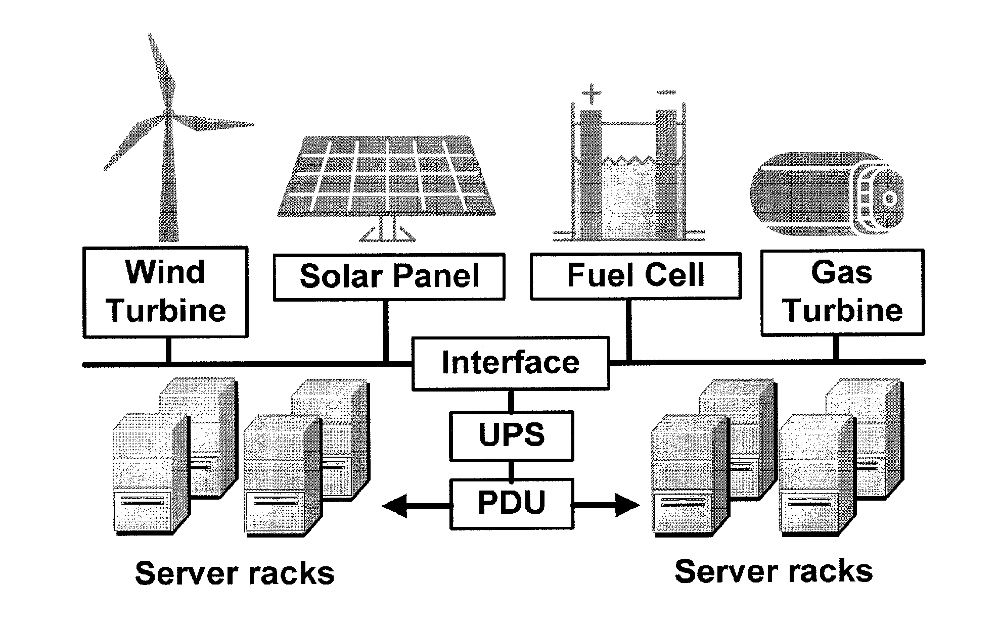
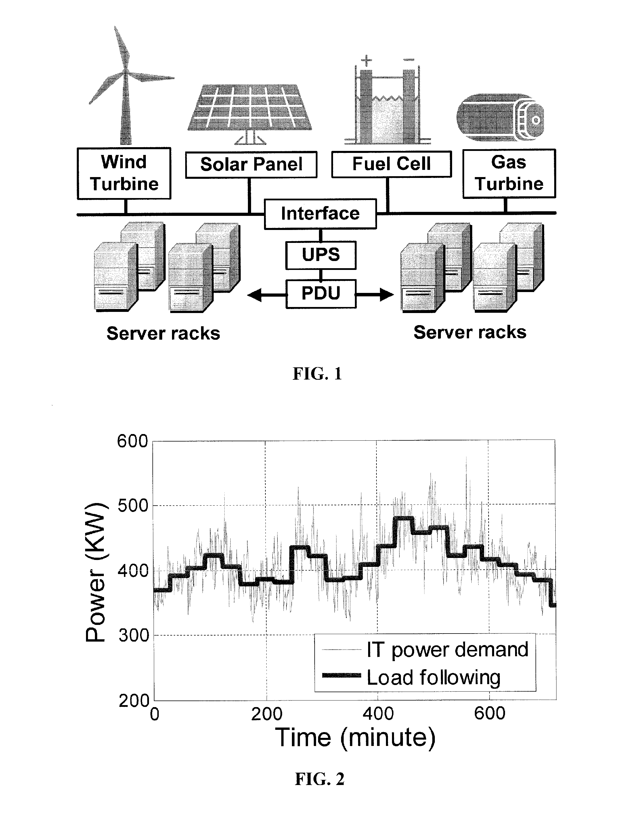
[0039]Embodiments of the invention relate to a method and system for power demand shaping (PDS) so as to manage power generation and use. Specific embodiments relate to data center power demand shaping to achieve high-performance low-overhead data center operation. Further specific embodiments can incorporate standard (utility power) energy sources, renewable energy sources, or a combination of standard (utility power) energy sources and renewable energy sources. Embodiments of the subject PDS techniques can incorporate trimming the data center load power so as to allow DG systems to follow the power demand efficiently and / or incorporate two adaptive load tuning schemes that can boost data center performance and enable near-oracle operation during power demand trimming process. To implement a cross-layer power optimization scheme, embodiments of the subject invention relate to a power management module that can reside between front-end distributed generation and back-end computing f...


PUM


Abstract

Embodiments relate to a method and system for power demand shaping (PDS) so as to manage power generation and use. Specific embodiments relate to data center power demand shaping to achieve high-performance low-overhead data center operation. Specific embodiments can incorporate standard (utility power) energy sources, renewable energy sources, or a combination of standard (utility power) energy sources and renewable energy sources. Embodiments of the subject PDS techniques can incorporate trimming the data center load power so as to allow DG systems to follow the power demand efficiently and/or incorporate two adaptive load tuning schemes that can boost data center performance and enable near-oracle operation during power demand trimming process. To implement a cross-layer power optimization scheme, embodiments of the subject invention relate to a power management module that can reside between front-end distributed generation and back-end computing facilities to provide a coordinated tuning between the supply and load.

Description

CROSS-REFERENCE TO RELATED APPLICATION[0001]The present application claims the benefit of U.S. Provisional Application Ser. No. 61 / 768,209 filed Feb. 22, 2013, which is hereby incorporated by reference herein in its entirety, including any figures, tables, or drawings.[0002]This invention was made with government support under CSR-1117261 awarded by National Science Foundation. The government has certain rights in this matter.BACKGROUND OF INVENTION[0003]Computer system design inevitably enters the landscape of design for sustainability as the data center power footprint has become a global concern. In the past ten years, Google server's electricity demand has increased almost 20-fold [1]. The huge IT energy consumption not only increases the total cost of ownership (TCO) but also leaves profound impact on the environment. According to a McKinsey Quarterly report, the annual CO2 emissions of computing systems will research 1.54 metric gigatons within eight years, which could make IT...

Claims


Application Information

Patent Timeline
Patent Type & Authority Applications(United States)
IPC IPC(8): H02J3/38H02J9/06
CPCH02J3/383H02J9/061H02J3/387H02J3/386H02J3/32Y02E70/30H02J2300/10H02J2300/20H02J3/381H02J3/004Y02E10/56Y02E10/76H02J2310/16H02J3/46H02J3/466
Inventor LI, TAOLI, CHAO
Owner UNIV OF FLORIDA RES FOUNDATION INC
Why Eureka
Try Eureka