Exhaust emission purifying apparatus for internal combustion engine

a technology for purifying apparatus and exhaust, which is applied in the direction of machines/engines, separation processes, instruments, etc., can solve the problems of short amount of reducing agent which reaches the reduction catalyst, and inability to achieve the desired exhaust emission purification performance. achieve the effect of reliability and achieving the desired exhaust emission purification performan

Active Publication Date: 2007-02-15
VOLVO LASTVAGNAR AB
View PDF16 Cites 59 Cited by
  • Summary
  • Abstract
  • Description
  • Claims
  • Application Information

AI Technical Summary

Benefits of technology

[0010] The present invention has an object to accelerate the mixing of the reducing agent with the exhaust gas to satisfactorily proceed with the reaction on the reduction catalyst, and to reliably achieve the desired exhaust emission purifying performance.

Problems solved by technology

However, the above described exhaust emission purifying apparatus for an engine has the following problems.
Therefore, the injected reducing agent is carried on the flow of the exhaust gas, and is difficult to sufficiently mix with the exhaust gas, and thus the reaction on the reduction catalyst does not proceed sufficiently so that the desired exhaust emission purifying performance cannot be achieved.
Further, since the nozzle hole is set to direct downward, the injected reducing agent is readily to be attached to a pipe wall bottom face of the exhaust passage, and a reducing agent amount which reaches the reduction catalyst tends to be short.
To increase an injection pressure of the reducing agent in order to accelerate the mixing of the reducing agent with the exhaust gas is not necessarily preferable, since there are problems in the excessive adding of the reducing agent and the running cost of the apparatus.
In the case where the reducing agent is excessively added due to the increase of the injection pressure, such a problem occurs that all of the added reducing agent might not be consumed in the reaction with NOx, and a partial reducing agent passes through the reduction catalyst to be discharged into the atmosphere.
Secondly, in this exhaust emission purifying apparatus, since the injection nozzle is disposed in a manner hanging from the pipe wall upper portion of the exhaust passage, the reducing agent is susceptible to the dripping after the injection.
If the deposition of the reducing agent occurs in the nozzle hole and at the periphery thereof due to this dripping, an amount of the reducing agent to be added lacks due to the clogging, resulting in the degradation of the exhaust emission purifying performance.
However, since this storage tank has a relatively large volume, a considerable amount of time is needed until the reducing agent is defrosted to enable the injection.
Therefore, the sufficient exhaust emission purifying performance cannot be achieved immediately after the engine operation is started.

Method used


Image

  • Exhaust emission purifying apparatus for internal combustion engine
  • Exhaust emission purifying apparatus for internal combustion engine
  • Exhaust emission purifying apparatus for internal combustion engine

Examples


first embodiment

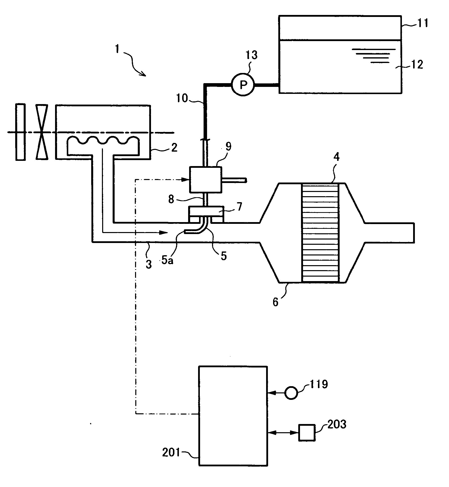
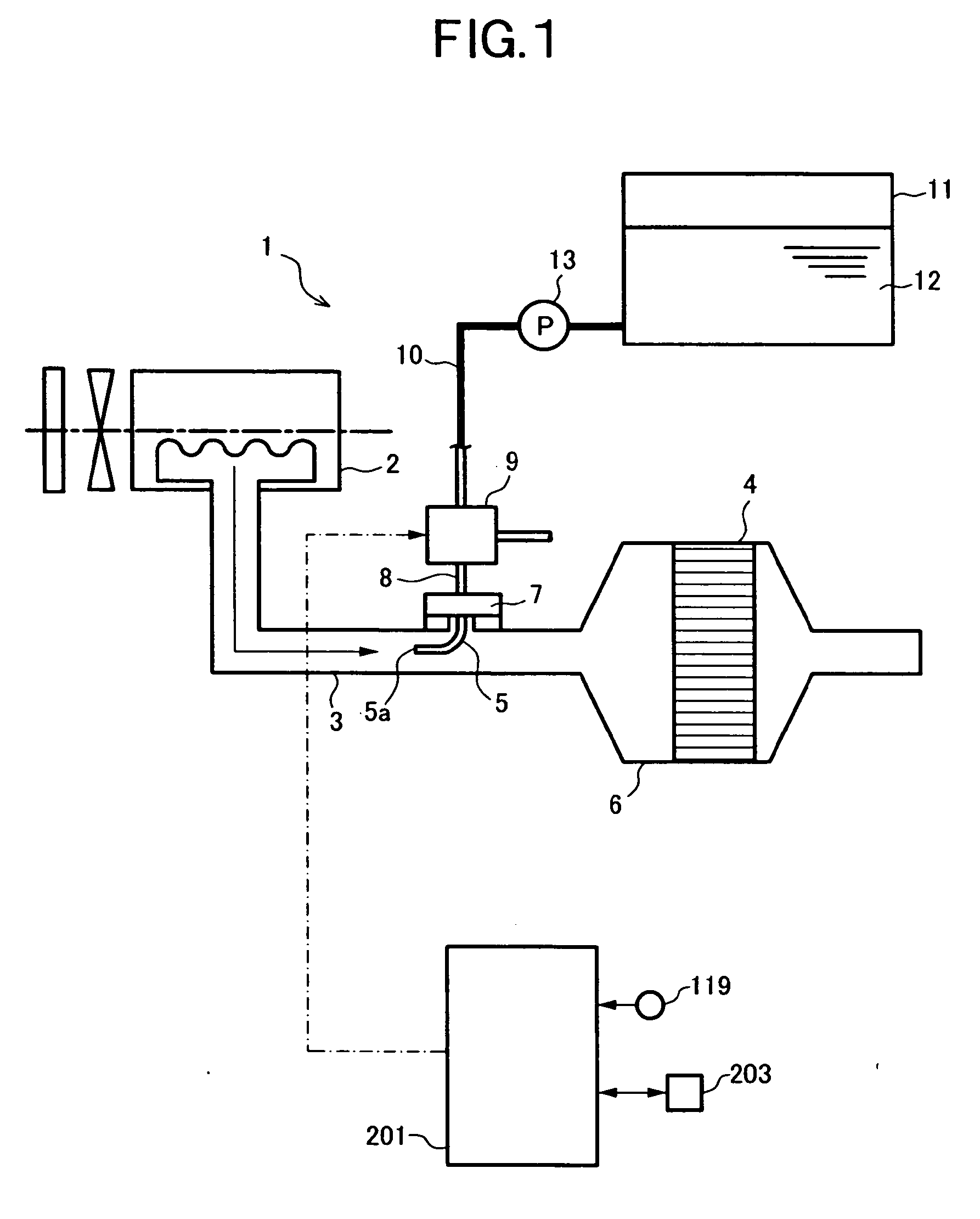
[0032]FIG. 1 shows a configuration of an internal combustion engine 1 (to be referred simply to as “engine” hereunder) which comprises an exhaust emission purifying apparatus according to the present invention. The engine 1 includes an exhaust passage 3 (which comprises an exhaust manifold and an exhaust pipe on the downstream thereof) connected to an engine body 2; a reduction catalyst 4 disposed in the exhaust passage 3; and an injection nozzle 5 disposed on the upstream of the reduction catalyst 4 in the exhaust passage 3. The exhaust emission purifying apparatus according to the present embodiment is for adding a reducing agent to the exhaust gas of the engine 1 by means of the injection nozzle, to purify NOx in the exhaust gas, and comprises a storage tank 11 to be described later and a SCR (Selective Catalytic Reduction) control unit 201, in addition to the reduction catalyst 4 and the injection nozzle 5. Incidentally, in this embodiment, the urea aqueous solution being ammoni...

second embodiment

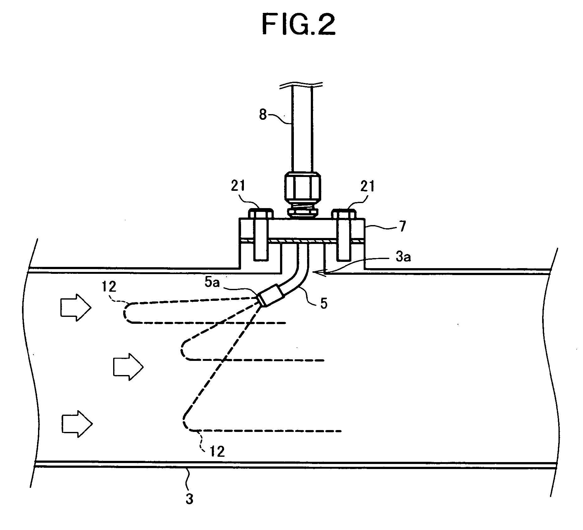
[0063]FIG. 5 shows a configuration of an attachment portion of the injection nozzle according to the present invention.

[0064] The injection nozzle 5 is attached to a pipe wall bottom portion of the exhaust passage 3 by means of the flange 7, and the nozzle hole 5a is set to open in a direction opposite to the flow of the exhaust gas, similarly to the nozzle hole 5a in the first embodiment. The injection nozzle 5 is arranged in the insertion hole 3a formed on the pipe wall of the exhaust passage 3. The flange 7 is fastened to the seating surface formed on the pipe wall of the exhaust passage by means of the bolts 21 to cover the insertion hole 3a.

[0065] According to the present embodiment, the urea water 12 is injected by the injection nozzle 5 toward the upstream against the flow of the exhaust gas, to be diffused strongly in the process of being pushed back by the flow of the exhaust gas, and therefore, the urea water 12 can be mixed with the exhaust gas. Particularly, according t...

third embodiment

[0066]FIG. 6 shows a configuration of the engine 1 including an exhaust emission purifying apparatus according to the present invention, and FIG. 7 shows a configuration of an attachment portion of the injection nozzle 5 according to the present embodiment.

[0067] The injection nozzle 5 is attached to the pipe wall bottom portion of the exhaust passage 3 by means of the flange 7, and the nozzle hole 5a thereof is set to be directed upward in a vertical direction. On the pipe wall of the exhaust passage 3, the insertion hole 3a for inserting therein the injection nozzle 5 is formed, and the injection nozzle 5 is arranged in this insertion hole 3a to be fixed in a state of standing upright from the pipe wall. The flange 7 is fastened to the seating surface formed on the pipe wall of the exhaust passage 3 by means of bolts 21 to cover the insertion hole 3a. The configuration of the storage tank 11 and the configuration of the control system (including the SCR control unit 201 and the he...


PUM


Abstract

In an exhaust emission purifying apparatus for an internal combustion engine, for adding a reducing agent for NOx to the exhaust gas to thereby purify NOx in the exhaust gas, the mixing of the reducing agent injected by an injection nozzle with the exhaust gas is accelerated. To this end, in the apparatus of the present invention, the injection nozzle for the urea water is disposed to be opposite to the flow of the exhaust gas, or to face upward in a vertical direction.

Description

[0001] This application is a continuation of PCT / JP2005 / 001529, filed on Feb. 2, 2005.BACKGROUND OF THE INVENTION [0002] 1. Field of the Invention [0003] The present invention relates to an exhaust emission purifying apparatus for an internal combustion engine, and in particular, to an exhaust emission purifying apparatus adopted for use in purifying nitrogen oxides (NOx) in the exhaust gas from an internal combustion engine by adding a reducing agent for the NOx to the exhaust gas through an injection nozzle disposed in an exhaust passage. [0004] 2. Description of the Related Art [0005] There has been known the following apparatus as an apparatus for purifying nitrogen oxides, or NOx, contained in the exhaust gas of an on-vehicle engine such as a diesel engine. Namely, in this apparatus, a reduction catalyst is disposed in an exhaust passage of the engine, and also, an injection nozzle for a reducing agent is disposed on the upstream of this reduction catalyst in the exhaust passag...

Claims


Application Information

Patent Timeline
Patent Type & Authority Applications(United States)
IPC IPC(8): G02B27/28B01D53/94F01N3/08F01N3/20F01N3/24
CPCB01D53/9409F01N3/206F01N3/2066F01N3/208F01N2610/02F01N2610/10Y02T10/24F01N2610/1453F01N2610/1466F01N2610/1486F01N2900/1811F01N2900/1818F01N2610/1406Y02T10/12
Inventor HIRATA, KIMINOBUMASAKI, NOBUHIKOAKAGAWA, HISASHIYAJIMA, YUJI
Owner VOLVO LASTVAGNAR AB
Why Eureka
Try Eureka