Chemical heat accumulator

a heat accumulator and chemical technology, applied in indirect heat exchangers, lighting and heating apparatus, greenhouse gas reduction, etc., can solve the problems of inability to discharge reacted materials, heat recovery operation may not be established, and heat generated is reduced, so as to enhance the efficiency of heat utilization and effective utilization

Inactive Publication Date: 2011-09-22
DENSO CORP
View PDF10 Cites 21 Cited by
  • Summary
  • Abstract
  • Description
  • Claims
  • Application Information

AI Technical Summary

Benefits of technology

[0017]In such a structure, the second reactant housed in the container of the first-stage heat storage unit is heated by heat from the heating source. Therefore, the advantages of the chemical heat accumulator according to the first aspect can be more reliably achieved.
[0019]In such a structure, the second reactant housed in the container of the first-stage heat storage unit is heated by heat of condensation generated when the gaseous second reactant is condensed. Therefore, the advantage of the chemical heat accumulator according to the fourth aspect can be achieved by such a simple configuration that the condenser is just provided with the thermal storage medium.
[0021]In such a structure, a surplus external heat generated at the external heat source is used to heat the second reactant housed in the container of the first-stage heat storage unit. Therefore, it is possible to effectively utilize the heat generated at the external heat source to enhance the efficiency of utilization of heat.

Problems solved by technology

For this reason, if such a heat recovery device is employed to a system involving such an amount-of-heat fluctuation that the amount of heat obtained from a heat engine is reduced with time, there is a possibility that the reaction material in the first chemical heat accumulator cannot discharge the reacted material because of an insufficient amount of heat.
Therefore, when the described heat recovery device is employed to a system utilizing exhaust heat from thermal components involving an amount-of-heat fluctuation, a problem that heat recovery operation is not established may arise.

Method used


Image

  • Chemical heat accumulator
  • Chemical heat accumulator
  • Chemical heat accumulator

Examples


first embodiment

[0050]A first embodiment will be described with reference to FIG. 1 to FIG. 7. A chemical heat accumulator according to the first embodiment stores solar heat and utilizes the stored heat at a heat engine when desired.

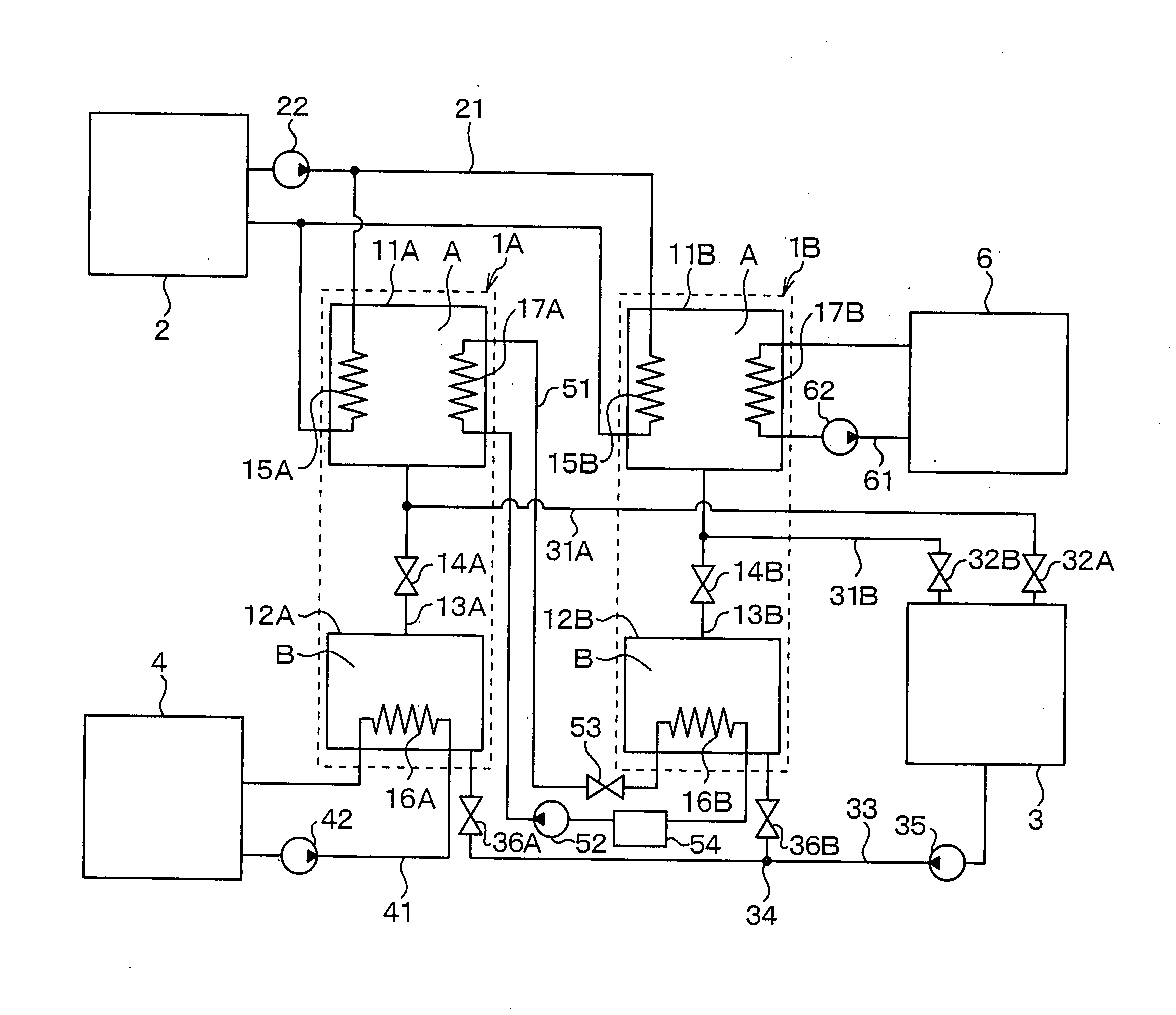
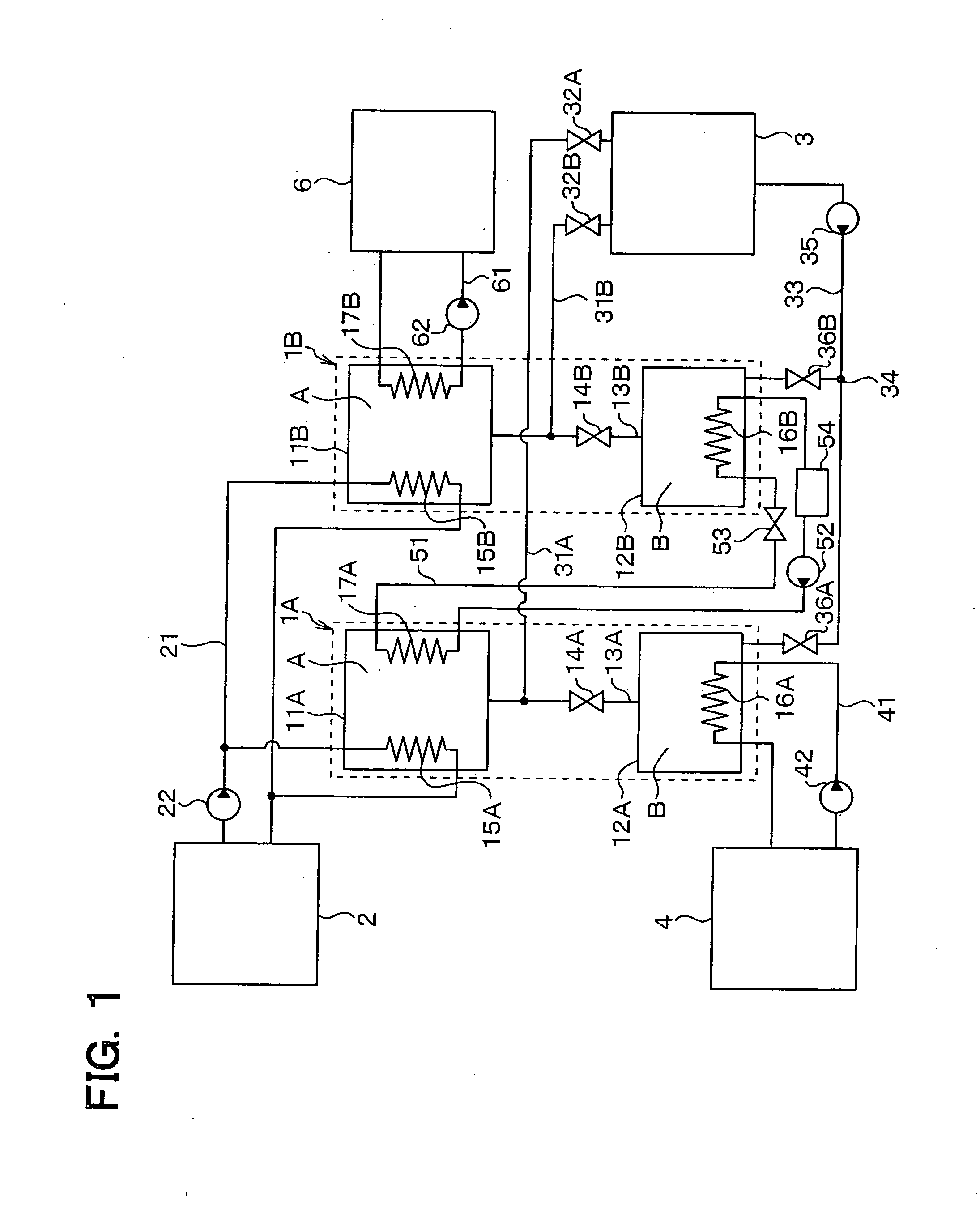
[0051]FIG. 1 is an overall block diagram illustrating the chemical heat accumulator according to the first embodiment. The chemical heat accumulator of the present embodiment can be switched between a heat release mode, a heat storage mode, and a heat storage sustainment mode. In the heat release mode, an object to be heated is heated by heat of reaction generated when a first reactant A and a second reactant B are caused to react with each other to produce a compound. In the heat storage mode, external heat that is generated outside a reaction system by separating a compound into a first reactant A and a second reactant B is stored. In the heat storage sustainment mode, a state in which external heat is stored is sustained.

[0052]In the present embodiment, calcium oxid...

second embodiment

[0127]A second embodiment will be described hereinafter with reference to FIG. 8. The second embodiment is different from the first embodiment in that the condenser inlet passages and the condenser outlet passage are eliminated and, instead, heat of the water vapor produced in the first and second reaction vessels 11A, 11B is exchanged with outside air through refrigerant.

[0128]FIG. 8 is an overall block diagram illustrating a chemical heat accumulator according to the second embodiment. As illustrated in FIG. 8, the chemical heat accumulator f the present embodiment is so configured that, in the heat storage mode, the water vapor produced in the first and second reaction vessels 11A, 11B flows into the first and second containers 12A, 12B through the connection passages 13A, 13B.

[0129]The chemical heat accumulator of the present embodiment includes: condensing heat exchangers 37A, 37B placed in the first and second containers 12A, 12B; a refrigerant refrigerator 30 placed outside t...

third embodiment

[0133]A third embodiment will be described with reference to FIG. 9. The third embodiment is different from the first embodiment in that part of heat of reaction generated in the first reaction vessel 11A is used as a heating source for heating water housed in the first container 12A.

[0134]FIG. 9 is an overall block diagram illustrating a chemical heat accumulator of the third embodiment. As illustrated in FIG. 9, the chemical heat accumulator of the present embodiment includes: a heat sourcing heat exchanger 43 placed in the first reaction vessel 11A; the first water heating heat exchanger 16A placed in the first container 12A; and a fifth heating medium circuit 44 that circulates a fifth heating medium between the heat sourcing heat exchanger 43 and the first water heating heat exchanger 16A.

[0135]The heat sourcing heat exchanger 43 is a heat exchanger that heats the fifth heating medium by heat of reaction generated when calcium oxide and water react with each other in the first ...


PUM

PropertyMeasurementUnit
temperatureaaaaaaaaaa
pressureaaaaaaaaaa
saturated vapor pressureaaaaaaaaaa

Abstract

A chemical heat accumulator includes first- to Mth-stage heat storage units and a condensing part. Each heat storage unit includes a reaction vessel housing first reactant, a container housing second reactant, and a connection passage connecting the reaction vessel and the container for guiding the second reactant from the container to the reaction vessel. The connection passage is provided with an opening / closing member for opening and closing the connection passage. The reaction vessel of the Mth-stage heat storage unit is thermally connected with an object to be heated. The reaction vessel of a (N−1)th-stage heat storage unit is thermally connected with the container of an Nth-stage heat storage unit. M is an integer equal to or greater than 2, and N is an integer equal to or greater than 2 and equal to or less than M.

Description

CROSS REFERENCE TO RELATED APPLICATION[0001]This application is based on Japanese Patent Applications No. 2010-65350 filed on Mar. 22, 2010 and No. 2010-267127 filed on Nov. 30, 2010, the disclosure of which are incorporated herein by reference.FIELD OF THE INVENTION[0002]The present invention relates to a chemical heat accumulator that utilizes the heat of reaction of a substance to extract heat and carries out pyrolysis to store heat.BACKGROUND OF THE INVENTION[0003]A heat recovery device that recovers exhaust heat from thermal components is, for example, described in JP-B2-8-6608 corresponding to U.S. Pat. No. 5,127,470. In the described heat recovery device, a reaction material in a first chemical heat accumulator is heated by high-temperature exhaust gas exhausted from thermal components to discharge reacted material, and a gas obtained as the result of heating the reaction material is subjected to heat recovery at a heat exchanger. Thereafter, a reacted material in a second ch...

Claims


Application Information

Patent Timeline
Patent Type & Authority Applications(United States)
IPC IPC(8): C09K5/16F24V30/00F24S10/30
CPCF28D7/022Y02E70/30Y02E60/142F28D20/003Y02E60/14
Inventor MIEDA, HIROSHI
Owner DENSO CORP
Why Eureka
Try Eureka