Control apparatus for an internal combustion engine and method for controlling the same

a technology of control apparatus and internal combustion engine, which is applied in the direction of electric control, machines/engines, instruments, etc., can solve problems such as burning fuel, and achieve the effect of achieving reliable control of the lift amoun

Inactive Publication Date: 2009-06-11
TOYOTA JIDOSHA KK
View PDF2 Cites 21 Cited by
  • Summary
  • Abstract
  • Description
  • Claims
  • Application Information

AI Technical Summary

Benefits of technology

[0030]According to the twelfth aspect, because it is possible to control the valve timing of the intake valve using an electrical motor, it is possible to reliably control the intake valve to a set lift amount, and possible to reliably achieve control of the lift amount in the above-noted six-stroke operation.

Problems solved by technology

However, in the case, for example, of a cold start of the internal combustion engine, in which there is a tendency for incomplete combustion to occur, there are cases in which the fuel is not completely combusted and non-combusted fuel remains that is exhausted from the cylinder in the exhaust stroke.

Method used


Image

  • Control apparatus for an internal combustion engine and method for controlling the same
  • Control apparatus for an internal combustion engine and method for controlling the same
  • Control apparatus for an internal combustion engine and method for controlling the same

Examples


first embodiment

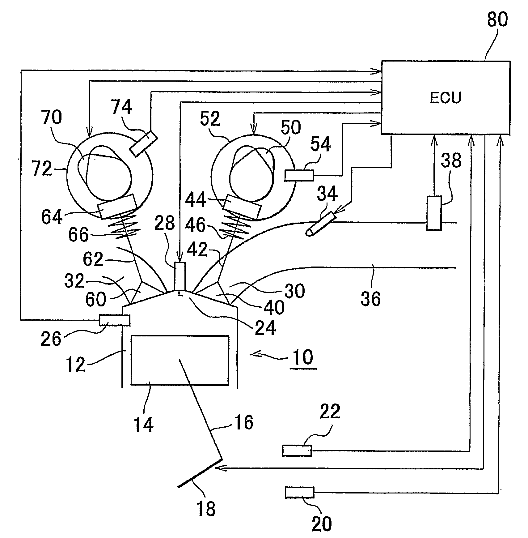
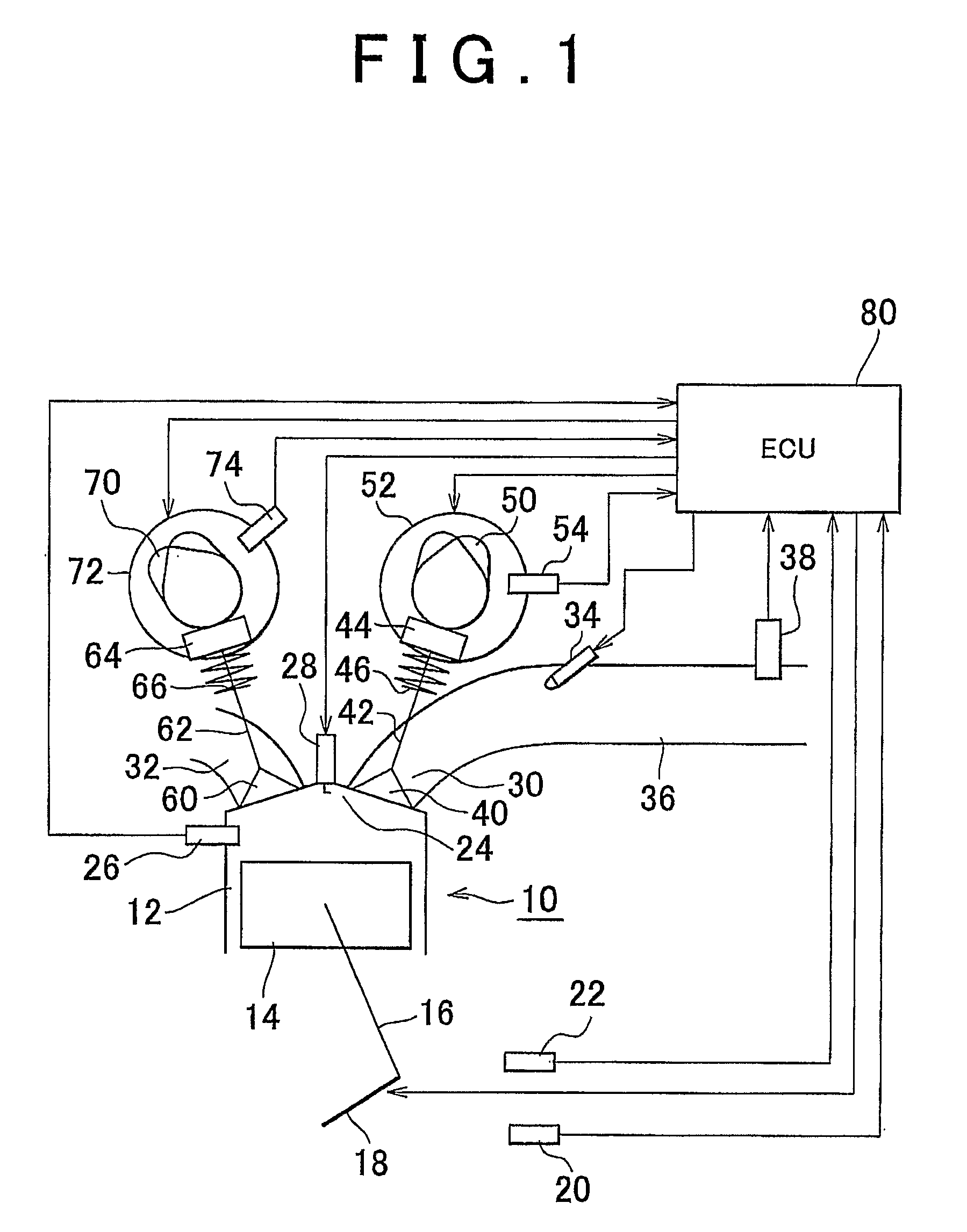
[0043]FIG. 1 is a schematic view showing the configuration of the present invention. The system shown in FIG. 1 has an internal combustion engine 10. The internal combustion engine 10 has a cylinder 12. Although only the cross-section of only one cylinder 12 is shown in FIG. 1, the internal combustion engine 10 actually has a plurality of cylinders 12. A piston 14 is disposed within the cylinder 12. The piston 14 is connected to a crankshaft 18 via a connecting rod 16. A rotational speed sensor 20 that generates an output responsive to the rotational speed of the crankshaft is disposed in the vicinity of the crankshaft 18. A coolant temperature sensor 22 that detects the temperature of the coolant for the internal combustion engine is provided in the internal combustion engine. A combustion chamber 24 is provided at the top of the piston 14. A temperature sensor 26 (temperature detecting means) that generates an output responsive to the temperature within the combustion chamber 24 i...

second embodiment

[0082]In six-stroke operation, an increase in the intake temperature makes it easier to burn the fuel. If the engine load becomes large under this condition, abnormal combustion tends to cause knocking. Also, if such abnormal combustion occurs, it can be assumed that the warm-up of the internal combustion engine 10 has progressed to some extent. In the second embodiment, therefore, in order to give priority to suppression of knocking, six-stroke operation is only permitted only when the engine load is within a range that does not cause knocking. The limit value of requested load set in consideration of occurrence of knocking, as indicated by the solid line (ii) in FIG. 5, is smaller than when the temperature of the coolant for the internal combustion engine 10 is high, and becomes higher when the coolant temperature is low. In consideration of suppression of knocking, the rise above the solid line (ii) in FIG. 5 (threshold engine load (ii)) is a second condition for switching from s...

third embodiment

[0093]Specifically, in the system of the third embodiment as well, six-stroke operation is performed at the cold start. It is possible to predict the temperature rise ΔT after the intake stroke in six-stroke operation, based on the air intake amount detected during the six-stroke operation. Therefore, the predicted temperature Tp in the combustion chamber 24 after the second intake stroke in six-stroke operation can be expressed by the current temperature T24 in the combustion chamber and the temperature rise ΔT in the form of Equation (1).

Predicted combustion chamber temperature Tp=Combustion chamber temperature T24+ΔT  (1)

[0094]Before starting six-stroke operation, even if the temperature in the combustion chamber 24 is lower than the threshold engine load, there are cases in which an excessive rise occurs in the intake temperature when six-stroke operation is actually performed. If ignition is done under the condition, because it may cause abnormal combustion or knocking to occur...


PUM


Abstract

In a control apparatus for an internal combustion engine having a valve timing control portion controlling the timing opening and closing of an intake valve disposed in an intake port communicating with a cylinder of the internal combustion engine, when the internal combustion engine is being started from a cold condition, multi-stroke operation is set, in which one combustion cycle of the internal combustion engine includes two or more intake and compression strokes, formed by a first intake stroke and the first compression stroke and a second intake stroke and compression stroke, followed by a combustion stroke and an exhaust stroke. The valve timing control portion controls a lift of the intake valve during the first intake stroke and the first compression stroke to a low lift amount, which is smaller than the normal lift amount required for intake of a requested intake air amount, and controls the lift of the intake valve in a second intake and a second compression stroke to the normal lift amount.

Description

BACKGROUND OF THE INVENTION[0001]1. Field of the Invention[0002]The present invention relates to a control apparatus for an internal combustion engine and a method for controlling an internal combustion engine. More specifically, it relates to a control apparatus for an internal combustion engine and a method for controlling an internal combustion engine capable of controlling the timing of the opening and closing and the lift amounts of individual intake valves of an internal combustion engine.[0003]2. Description of the Related Art[0004]The Japanese Patent Application Publication No. JP-A-10-252511 discloses a system that controls the opening and closing of the intake valve and exhaust valve by a valve driving mechanism capable of variably adjusting the timing of the opening and closing of intake and exhaust valves disposed in each cylinder of an internal combustion engine. In this system, during normal operation, in which combustion in the internal combustion engine is stable, th...

Claims


Application Information

Patent Timeline
Patent Type & Authority Applications(United States)
IPC IPC(8): F01L1/34
CPCF01L1/34Y02T10/36F01L2800/00F01L2800/01F02D13/0226F02D13/0273F02D41/0002F02D41/0025F02D41/064F02D41/068F02D41/3058F02D2013/0292F02D2041/001F02D2200/0611Y02T10/18F02D19/084F01L1/36Y02T10/12Y02T10/30
Inventor KAWAI, TAKASHI
Owner TOYOTA JIDOSHA KK
Why Eureka
Try Eureka