Aerial digital camera and method of controlling the same

a technology of aerial digital camera and digital camera, which is applied in the field of aerial digital camera and to the method of controlling the same, can solve problems such as adversely affecting the accuracy, and achieve the effect of reducing blur in the recorded image and high number of repetition cycles of accurate sensor movemen

Active Publication Date: 2013-10-01
TRIMBLE GERMANY
View PDF18 Cites 21 Cited by
  • Summary
  • Abstract
  • Description
  • Claims
  • Application Information

AI Technical Summary

Benefits of technology

[0006]Embodiments of aerial digital cameras comprise a housing, a lens adapter mounted on the housing and configured to receive a lens, a frame, an image sensor mounted on the frame, and at least three flexure bearings connecting the frame and the housing, wherein the flexure bearings allow for a displacement of the frame relative to the housing in a displacement direction parallel to a light receiving surface of the image sensor, and an actuator configured to displace the frame relative to the housing in the displacement direction. It is possible to mount and orient the camera on a vehicle such that the displacement direction of the camera is oriented in the motion direction of the vehicle relative to the object to be imaged and to control the actuator such that it moves the frame and image sensor in the displacement direction during exposure of the image sensor to reduce blur in the recorded image.
[0007]According to exemplary embodiments, the camera comprises a spring providing a biasing force between the housing and the frame, wherein the biasing force is oriented in the displacement direction, and wherein the actuator is configured to apply a force opposite to the biasing force of the spring to the frame such that the actuator can displace the frame relative to the housing against the biasing force of the spring. Such configuration may allow for a precise displacement of the frame relative to the housing in repetitive movement cycles. In particular, such configuration may prevent the mechanical play which inevitably remains in mechanical components of the actuator from adversely affecting the accuracy of the sensor movement controlled by the actuator.
[0008]According to some embodiments, the actuator comprises a motor, a cam rotatably supported on the housing and driven by the motor, and a cam follower engaging the cam, wherein a component of the cam follower abuts against the frame. The combination of a cam and a cam follower displacing the frame carrying the image sensor against the biasing force of a spring has been found reliable for achieving a high number of repetition cycles of accurate sensor movement.
[0010]According to some embodiments, at least one of the at least three flexure bearings includes an elongated strip of a flexible material. The elongated strip has a cross section which is in itself elongated such that a dimension of the cross section in one direction is substantially greater, such as five or even more greater, than in a direction orthogonal thereto. With such configuration, the flexure bearing defines the direction into which the frame and image sensor can be displaced relative to the housing, such that other mechanical structures, such as guiding rails or other which might produce friction, can be avoided.
[0013]According to further embodiments, the control system is configured to control the actuator by triggering an image sensor movement cycle comprising accelerating the image sensor and maintaining the image sensor at a constant sensor velocity during a time interval including the opening of the shutter and the closing of the shutter. It is desirable that the image sensor is already moving at its constant velocity when the opening of the shutter is completed and / or when the exposure of the image sensor begins. It is therefore advisable, to trigger the image sensor movement cycle a sufficient time before the opening of the shutter is completed since some time is needed to accelerate the image sensor until it reaches its desired constant velocity, and wherein additional time can be provided during which vibrations of the image sensor caused by the acceleration may decay.

Problems solved by technology

In particular, such configuration may prevent the mechanical play which inevitably remains in mechanical components of the actuator from adversely affecting the accuracy of the sensor movement controlled by the actuator.

Method used


Image

  • Aerial digital camera and method of controlling the same
  • Aerial digital camera and method of controlling the same
  • Aerial digital camera and method of controlling the same

Examples


Embodiment Construction

[0034]In the exemplary embodiments described below, components that are alike in function and structure are designated as far as possible by like reference numerals. Therefore, to understand the features of the individual components of a specific embodiment, the descriptions of other embodiments and of the summary of the invention should be referred to.

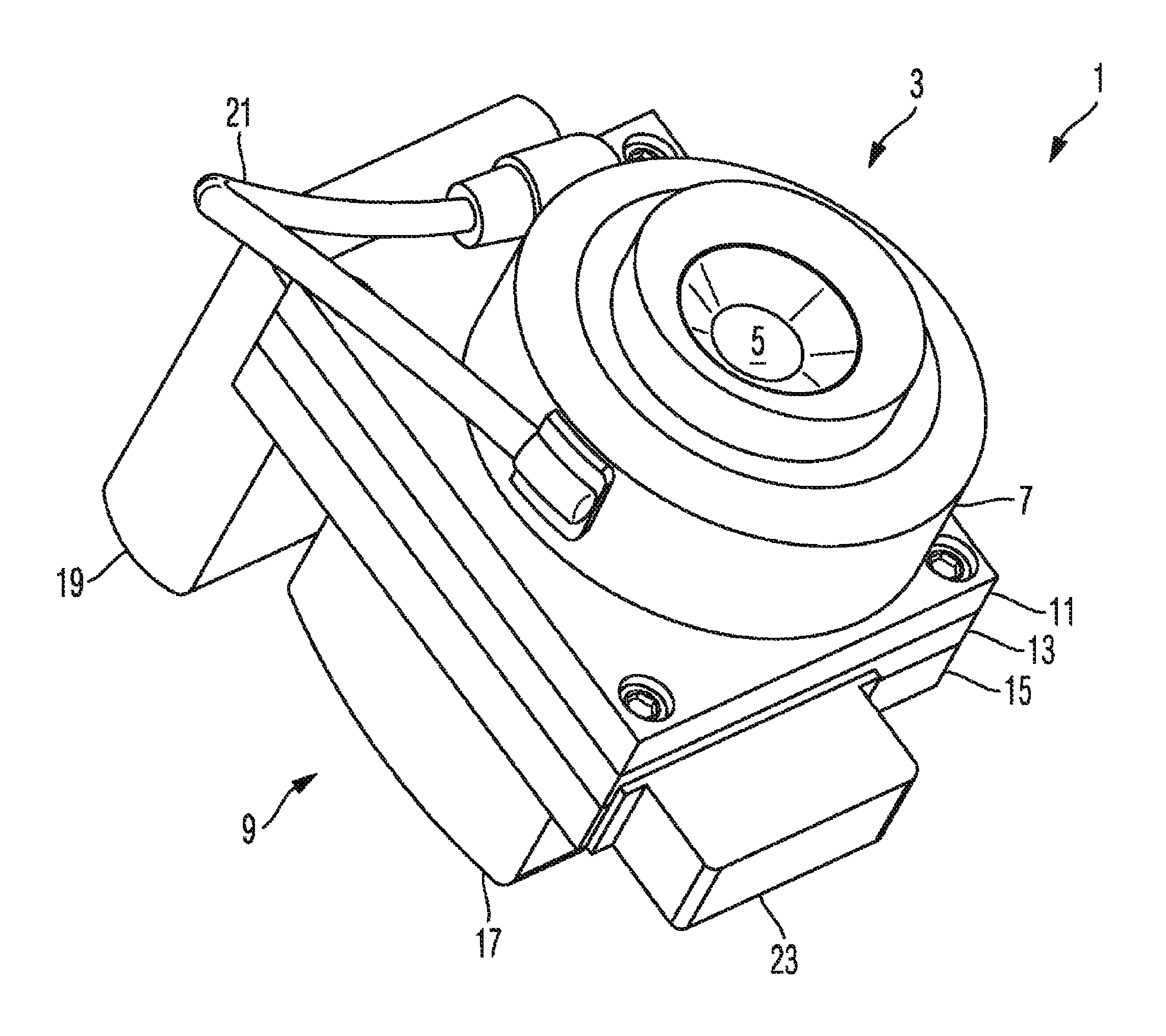
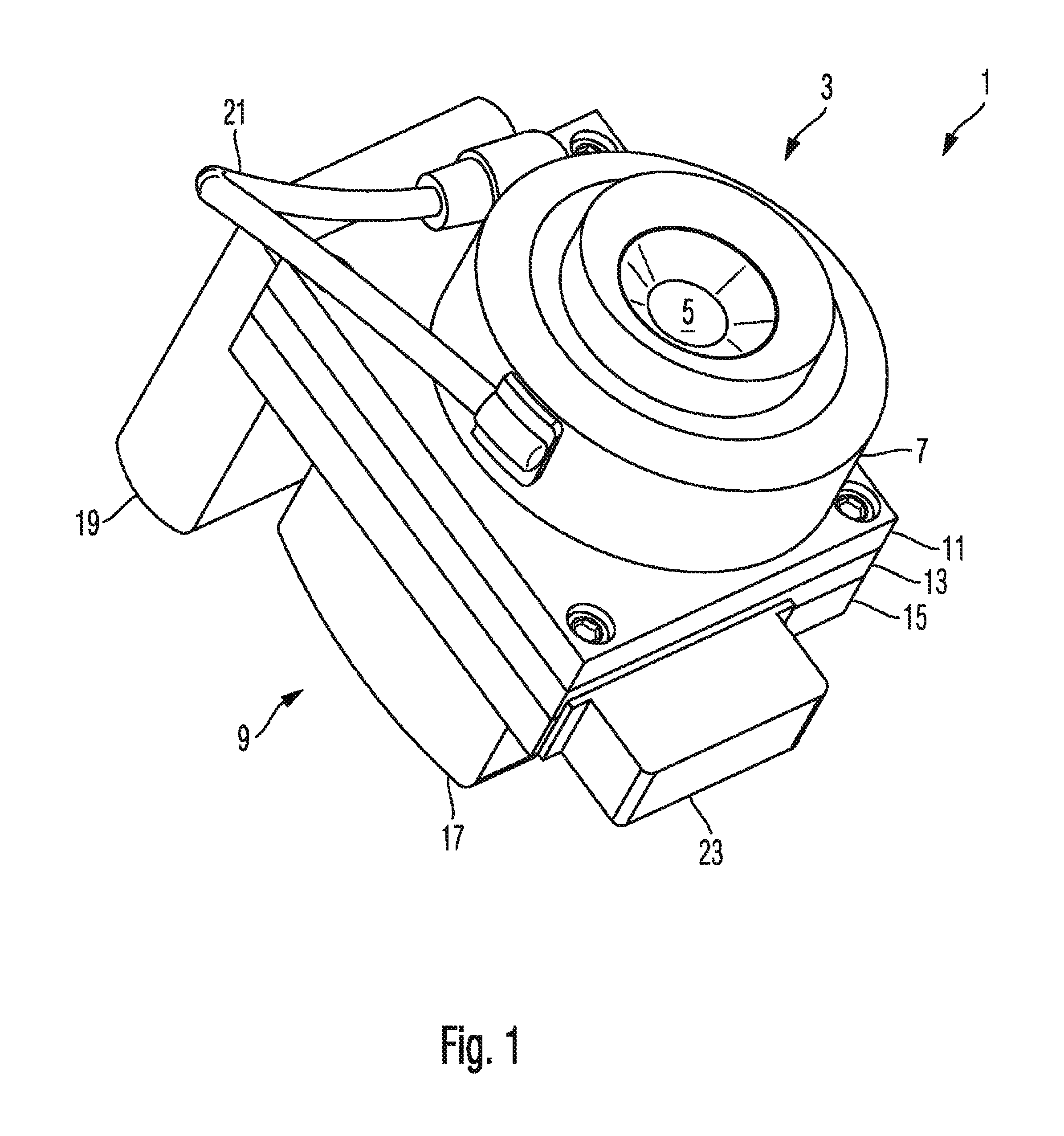
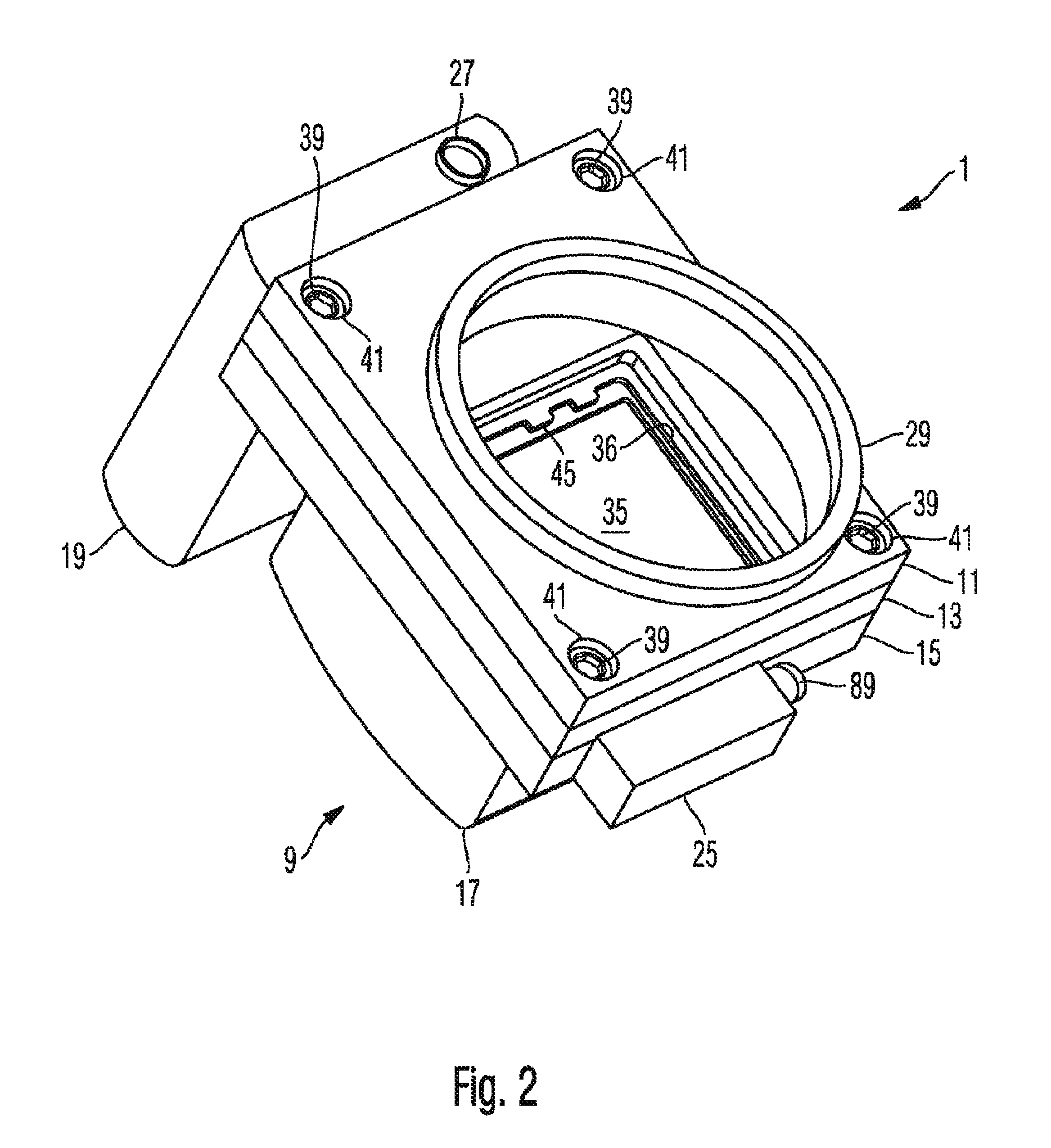
[0035]An exemplary embodiment of an aerial digital camera will be illustrated below with reference to FIGS. 1 to 7. FIG. 1 is a schematic perspective illustration of the camera 1. The camera comprises a lens 3 including a lens barrel, wherein a front lens 5 of the lens barrel is visible in FIG. 1. The lens 3 further includes a mechanical shutter positioned in an aperture plane of the lens barrel, wherein a housing of components of the shutter, such as blades and actuators of the shutter is indicated in FIG. 1 at 7.

[0036]The camera 1 further comprises a housing 9 comprising plural plates 11, 13, 15 and a cover 17. An electronic control...


PUM

PropertyMeasurementUnit
thicknessaaaaaaaaaa
thicknessaaaaaaaaaa
lengthaaaaaaaaaa

Abstract

An aerial digital camera comprises a housing 15, a lens, a frame 45, an image sensor 35 mounted on the frame, at least three flexure bearings 51 connecting the frame and the housing, the flexure bearings allowing a displacement of the frame relative to the housing in a displacement direction 67 parallel to a light receiving surface of the image sensor, a spring 69 providing a biasing force between the housing and the frame oriented in the displacement direction; and an actuator 71 for displacing the frame relative to the housing against the biasing force of the spring.

Description

RELATED APPLICATION[0001]This application claims benefit of U.S. Provisional Application for Patent No. 61 / 404,296 filed 30 September 2010, the entire content of which is incorporated herein by this reference.FIELD OF THE INVENTION[0002]The present disclosure relates to aerial digital cameras and to methods of controlling aerial digital cameras. In particular, the disclosure relates to aerial digital cameras which allow for forward motion compensation.BACKGROUND OF THE INVENTION[0003]An aerial digital camera can be mounted on an aircraft, satellite or other vehicle to record images of distant objects. The forward motion of the vehicle at the time of image exposure leads to a blurring (dragging) of the recorded image. The blurring increases with exposure time, speed of the vehicle relative to the object and inversely with distance of the camera from the object. Forward motion compensation (FMC) is applied to compensate for the forward movement of the vehicle in order to reduce or eli...

Claims


Application Information

Patent Timeline
Patent Type & Authority Patents(United States)
IPC IPC(8): G03B39/00
CPCG01C11/02G03B5/00H04N5/2253H04N5/23258H04N5/23287H04N5/2252G03B15/006G03B2205/0092G03B2205/00H04N23/54H04N23/6812H04N23/687Y10T29/49716H04N23/51
Inventor KRUEGER, ROLAND
Owner TRIMBLE GERMANY
Why Eureka
Try Eureka