Focusing and focus metrics for a plenoptic imaging system

a plenoptic imaging and focus metric technology, applied in the field can solve the problems of limited literature on the optical design of plenoptic imaging systems that go beyond geometric optics considerations, and little literature explaining how to design, manufacture or assemble plenoptic imaging systems, and achieve the effect of reducing the blur in the pupil imag

Inactive Publication Date: 2013-09-10
RICOH KK
View PDF45 Cites 41 Cited by
  • Summary
  • Abstract
  • Description
  • Claims
  • Application Information

AI Technical Summary

Benefits of technology

[0010]Furthermore, the axial position of the sensor array relative to the secondary imaging array can be adjusted based on reducing a blur in a pupil image function of the plenoptic imaging system. In addition, the distance to the object can be estimated once the in-focus positions of the secondary imaging array and / or sensor array have been determined.

Problems solved by technology

However, there is limited literature on the optical design of a plenoptic imaging system that goes beyond geometric optics considerations.
However, there is not much literature explaining how to actually design, manufacture or assemble plenoptic imaging systems.
However, a plenoptic imaging system that is “in focus” does not produce a sharp image of the object at the sensor array.
Therefore, conventional focusing criteria are not appropriate for focusing a plenoptic system.

Method used


Image

  • Focusing and focus metrics for a plenoptic imaging system
  • Focusing and focus metrics for a plenoptic imaging system
  • Focusing and focus metrics for a plenoptic imaging system

Examples


example automated

[0068 Alignment

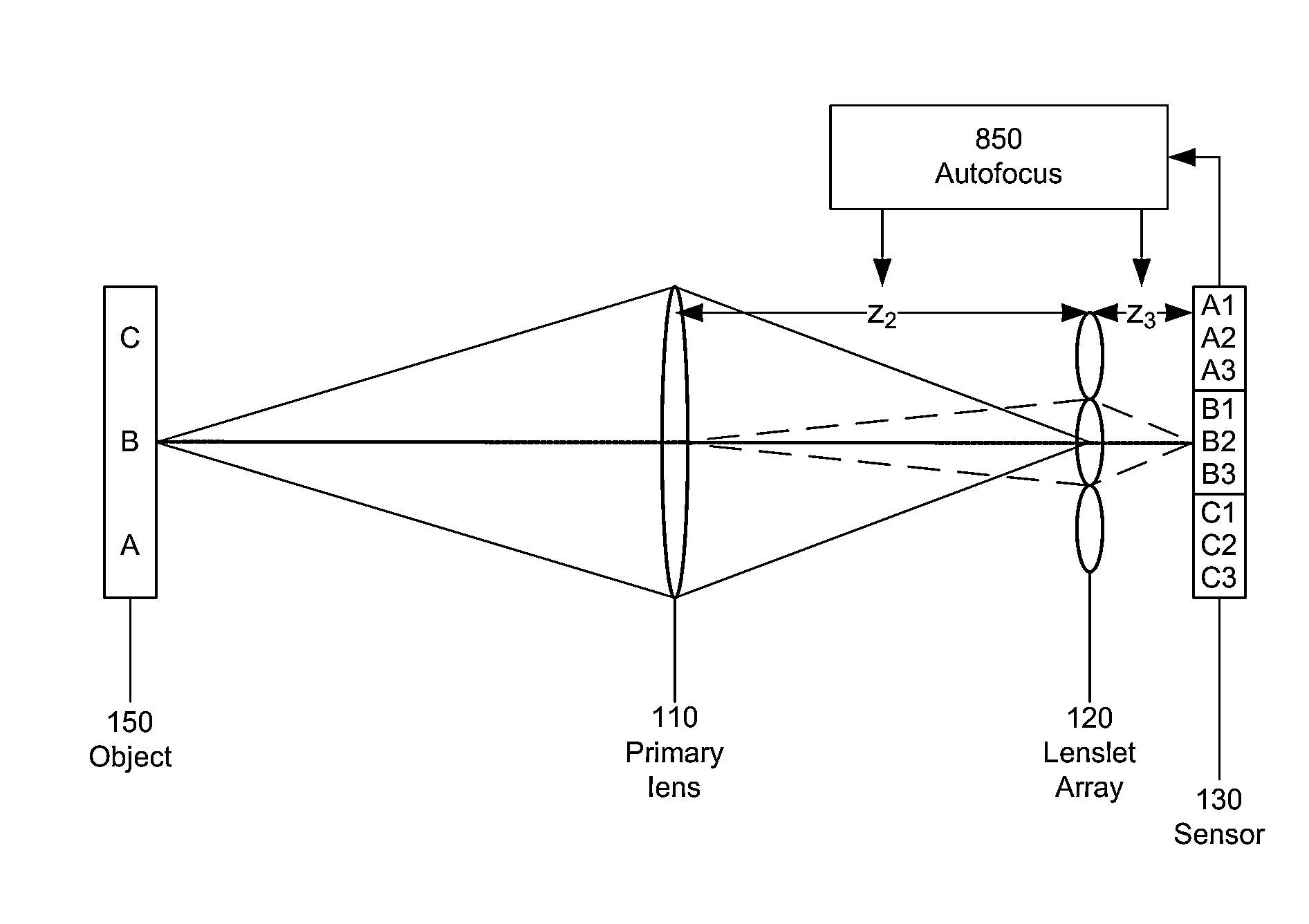
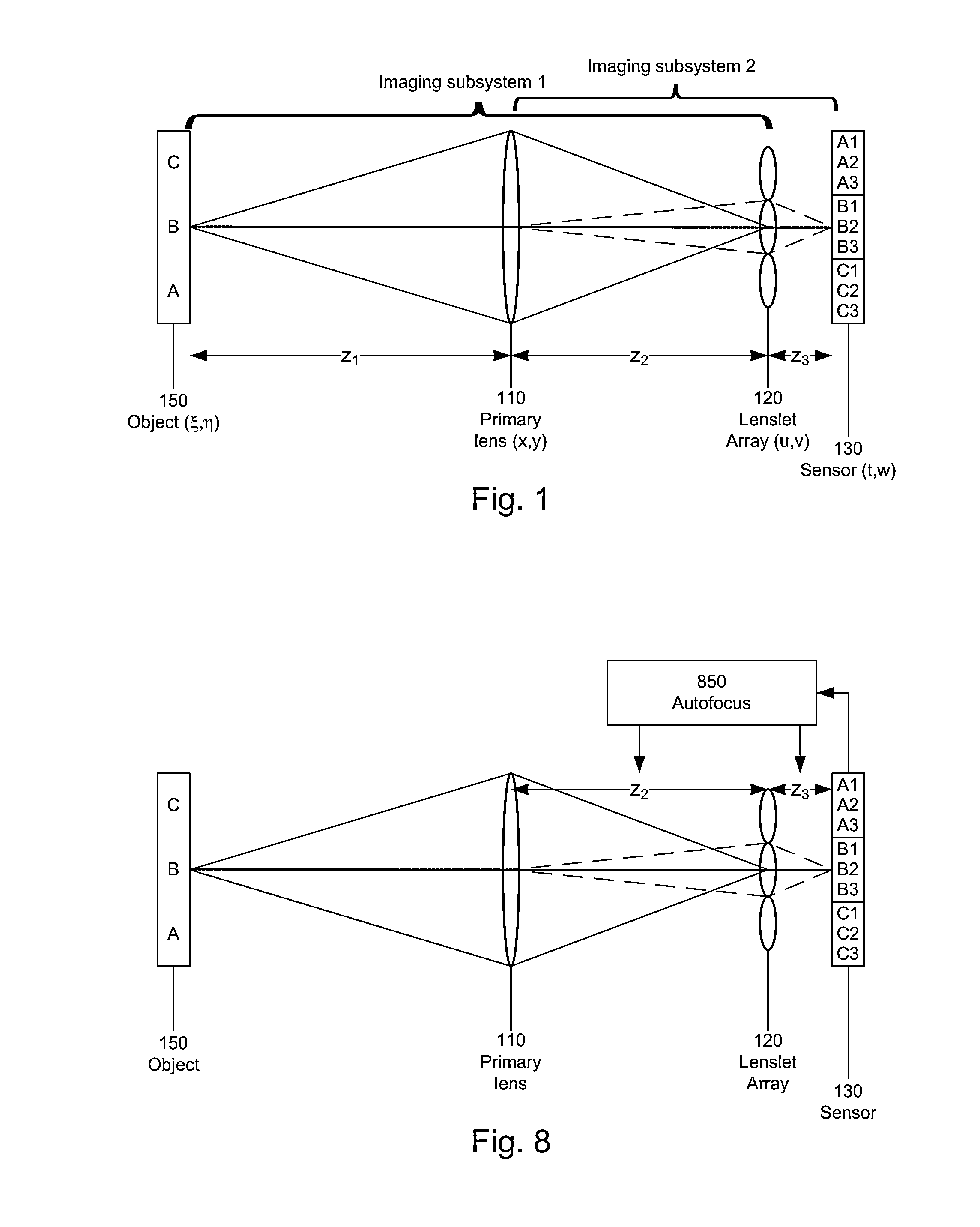
[0069]FIG. 5 is a flow diagram for aligning a plenoptic imaging system, based on the principles described above. In this example, it is assumed that the object is at an unknown object distance z1, so that it is not possible to accurately calculate z2 and z3. Instead, z2 and z3 are adjusted as follows. As an initial setting, z3 is set 510 to f2. Then z2 is adjusted 520 based on increasing the high frequency content in the plenoptic image captured by the sensor array. Then z3 is adjusted 530 based on reducing blur in the PIF. Steps 520 and 530 may be iterated, or interchanged. Alternately, z2 and z3 may be adjusted simultaneously based on a metric that accounts for both the high frequency and blur characteristics. More details are given below, using the example plenoptic imaging system introduced previously.

[0070]In step 510, the sensor array is moved to the back focal plane of the lenslet array, i.e. z3=f2=5 mm. This can be done experimentally using collimated light an...


PUM


Abstract

Metrics for characterizing the focusing of a plenoptic imaging system. In one aspect, the metric is based on the high frequency content and / or the blurring of the plenoptic image.

Description

BACKGROUND OF THE INVENTION[0001]1. Field of the Invention[0002]This invention relates generally to plenoptic imaging systems, and more particularly to focusing of plenoptic imaging systems.[0003]2. Description of the Related Art[0004]The plenoptic imaging system has recently received increased attention. It can be used to recalculate a different focus point or point of view of an object, based on digital processing of the captured plenoptic image. The plenoptic system also finds application in multi-modal imaging, using a multi-modal filter array in the plane of the pupil aperture. Each filter is imaged at the sensor, effectively producing a multiplexed image of the object for each imaging modality at the filter plane. Other applications for plenoptic imaging systems include varying depth of field imaging and high dynamic range imaging.[0005]However, there is limited literature on the optical design of a plenoptic imaging system that goes beyond geometric optics considerations. Thu...

Claims


Application Information

Patent Timeline
Patent Type & Authority Patents(United States)
IPC IPC(8): H04N5/225H04N5/232
CPCH04N5/23212G02B7/38G06F17/5009H04N23/957H04N23/673G06F30/20
Inventor SHROFF, SAPNA A.BERKNER, KATHRINSTORK, DAVID G.
Owner RICOH KK
Why Eureka
Try Eureka