Computer mouse having side areas to maintain a depressed button position

a mouse and button technology, applied in computing, instruments, electric digital data processing, etc., can solve the problem that the separate button located at the front of the mouse can be uncomfortable for people with very large hands

Inactive Publication Date: 2005-01-18
APPLE INC
View PDF6 Cites 158 Cited by
  • Summary
  • Abstract
  • Description
  • Claims
  • Application Information

AI Technical Summary

Problems solved by technology

However, having a separate button located at the front of a mouse can be uncomfortable for those with very large hands, very small hands or deformed hands.

Method used


Image

  • Computer mouse having side areas to maintain a depressed button position
  • Computer mouse having side areas to maintain a depressed button position
  • Computer mouse having side areas to maintain a depressed button position

Examples


Embodiment Construction

The following description provides embodiments of the present invention. However, it will be appreciated that other embodiments of the present invention will become apparent to those of ordinary skill in the art upon examination of this description. Thus, the present description and accompanying drawings are for purposes of illustration and are not to be used to construe the invention in a restrictive manner.

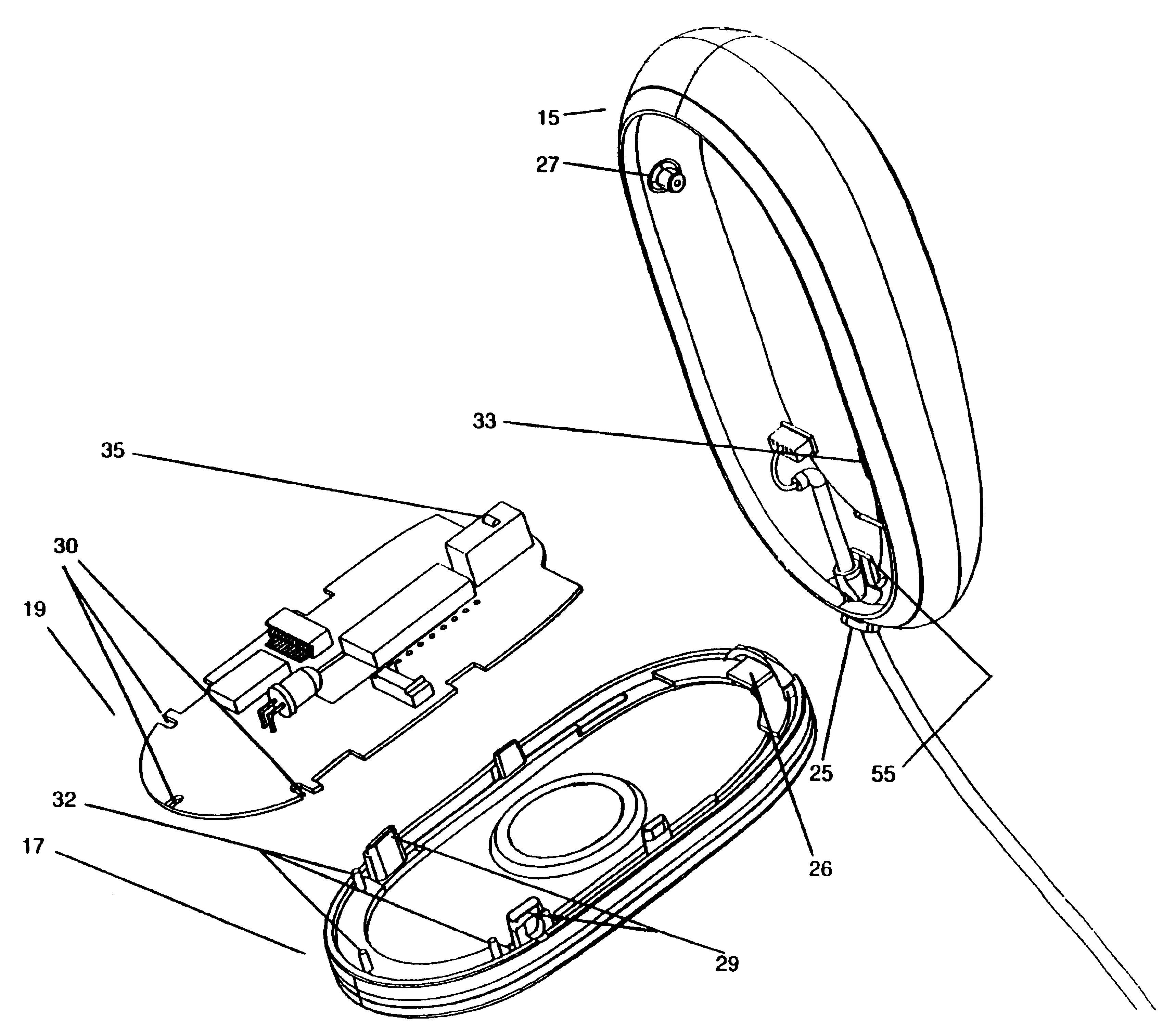
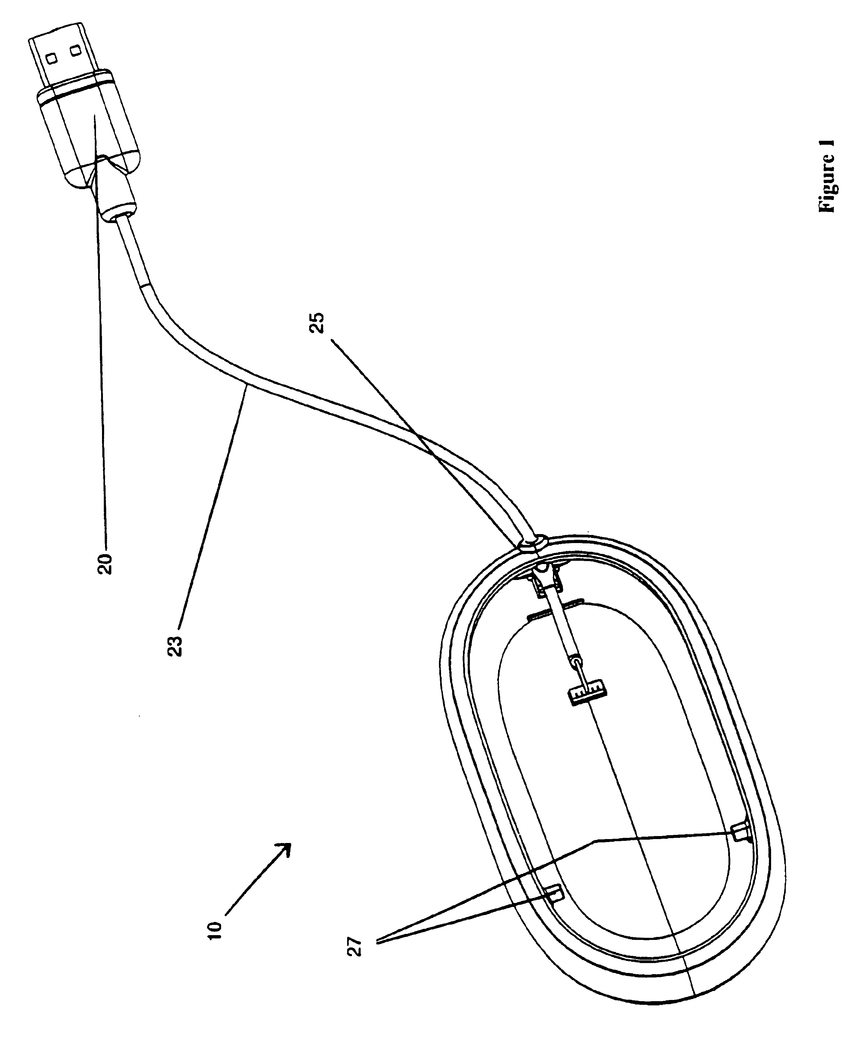
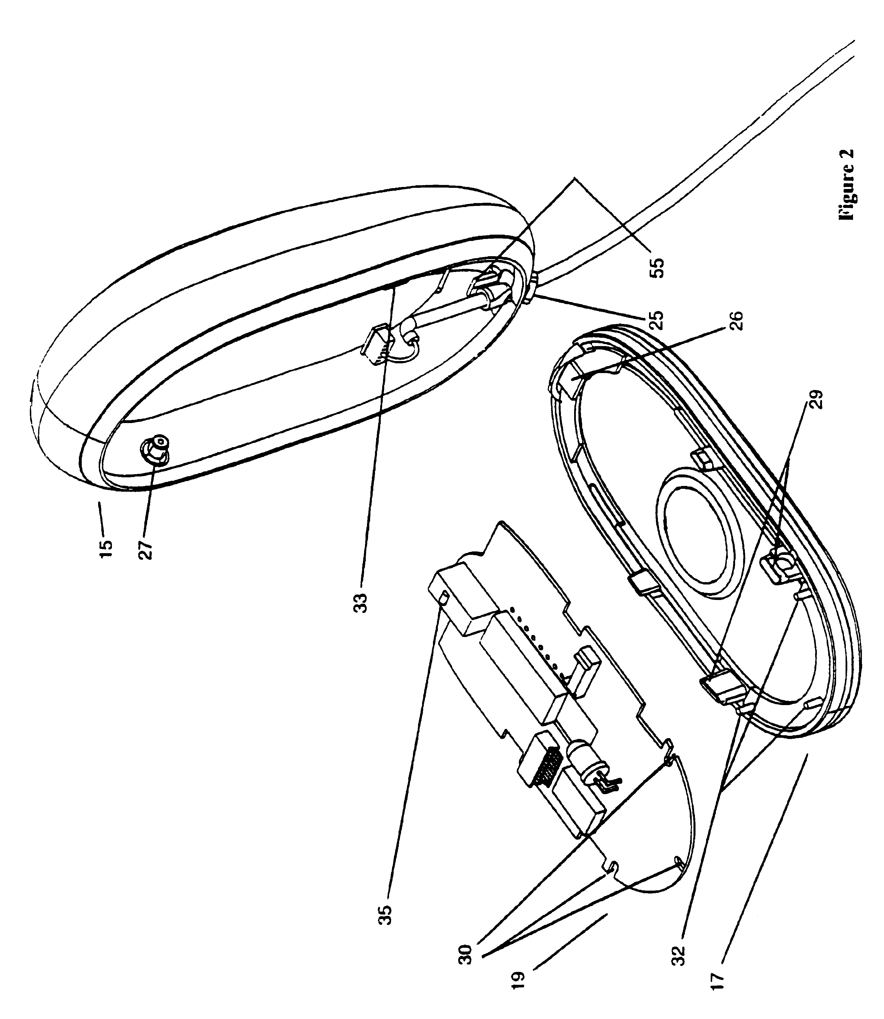
FIGS. 1 and 2 illustrate two views of a computer mouse 10 which includes a top member 15, a base member 17 and a printed circuit board (PCB) member 19. Top member 15 and base member 17 together form the housing of mouse 10. In one embodiment, portions of top member 15 and base member 17 are translucent to provide views of the internal electronics of mouse 10. It should be noted that, for the purpose of clarity, not all of the internal components of mouse 10 are shown. Furthermore, it is appreciated that mouse 10 may use a mechanical system (e.g., captured ball) or an optical sys...


PUM


Abstract

A computer mouse having a base member with hold regions. A top member is pivotally coupled to the base member and covers the internal electronics of the mouse. The top member has a main surface with openings to accommodate the hold regions of the base member and leave them exposed to a user's fingers. The top member also acts as a button for the mouse. The hold regions allow a user to lift the mouse while maintaining the top member in a depressed position.

Description

BACKGROUND OF THE INVENTION1. Field of the InventionThe present invention relates generally to cursor control devices for use in conjunction with a computer system.2. Background InformationCursor control devices exist in a number of forms, such as joysticks, trackballs, styli and pads, and mice. The computer mouse has been and continues to be a widely used cursor control device. A typical mouse has a body which houses a captured ball, a portion of which extends from the interior of the body. A typical mouse is moved over a flat surface such that the captured ball is in contact with the surface and rolls along the surface in the same direction as the mouse body. The movement of the ball generates two-dimensional data input for corresponding cursor control, the results of which are visible on a display device of the computer. Instead of using a captured ball, a mouse may use optical electronics to generate cursor control signals. A typical mouse also includes an electromechanical swit...

Claims


Application Information

Patent Timeline
Patent Type & Authority Patents(United States)
IPC IPC(8): G06F3/033
CPCG06F3/03543G06F2203/0333
Inventor FARAG, ABRAHAM S.ANDRE, BARTLEY K.
Owner APPLE INC
Why Eureka
Try Eureka