Pressure relief device

Active Publication Date: 2005-02-08
WESTPORT FUEL SYST CANADA INC
View PDF93 Cites 16 Cited by
  • Summary
  • Abstract
  • Description
  • Claims
  • Application Information

AI Technical Summary

Benefits of technology

In another alternative aspect, there is provided a pressure relief device having a housing including an inlet, an outlet and an inner wall defining a cavity. The cavity includes a passage for flow of fluid between the inlet and the outlet. The cavity also includes a chamber contiguous with the passage. The inlet is in communication with a fluid under pressure in a pressure vessel. The pressure relief device also includes a plug positioned in the cavity. The plug is movable between a closed position, in which a flow of the fluid through the passage is blocked, and an open position, in which the flow of the fluid is permitted through the passage in response to a pressure differential between the inlet and the outlet. The plug includes a plug contact surface adapted to cooperate with the inner wall to define one or more voids therebetween when the plug is in the closed position. The pressure relief device also includes a temperature-sensitive bonding material receivable in the voids. The bonding material is adapted to release the plug surface upon exposure to a predetermined temperature so that the plug is movable from the closed position to the open position. The bonding material bonds the plug contact surface to the inner wall to maintain the plug in the closed position until the bonding material is exposed to at least the predetermined temperature.
The pressure relief device also includes a biasing means for urging the plug into the open position. The biasing means is resistable by the bonding material until the bonding material is exposed to at least the predetermined temperature. The plus also includes a plug bore for maintaining communication between the inlet and the chamb

Problems solved by technology

Such excess pressure may be caused, for example, by a fire.
However, fire does not always result in excess pressure.
In these circumstances, however, the fire would weaken the tank wall, resulting in a dangerous situation.
Known pressure relief devices are designed to function in the event that a fire breaks out at or near the pressure vessel, resulting in a risk of explosion or collapse of the pressure vessel.
Partial blockage is undesirable because it would impede the flow of fluid through the passage.
However, known pressure relief devices suffer from a number of defects.
For example, because the pressure relief device typically remains in the closed position for an extended period of time, the fusible alloy may creep (i.e., deform over time under stress) because of the stress imposed on the fusible alloy by the pressure force from the fluid and / or the spring.
Ultimately, creep can result in the plug moving to the open position (or a partly open position). and consequent release of the fluid, in circumstances where release of the fluid is neither necessary nor desirable.
Another defect of conventional pressure relief devices is that, in some devices, the movement of the plug to the open position results in the expulsion of the plug from the pressure relief device at a relatively high velocity.
The sudden expulsion of the plug can be dangerous and damaging.
However, conventional pressure relief devices typically include a number of sharp edges or sharp corners in the passage which is opened up when the plug moves to the open position.
In addition, known pressure relief devices also tend to have a relatively large number of mechanical parts, so that the risk of failure or malfunctioning of these devices is relatively high.
However, when the plug moves to the open position, the seal member is in the path of the fluid, and the seal member therefore tends to obstruct the fluid flow through the passage in the pressure relief device.

Method used


Image

  • Pressure relief device
  • Pressure relief device
  • Pressure relief device

Examples


embodiment 200

In FIG. 9, an alternative embodiment 200 of the pressure relief device is shown. The pressure relief device 200 includes a plug 234 (shown in an open position in FIG. 9) in which a tapered contact surface 236 extends to a point 275. The plug 234 therefore does not include a cone portion corresponding to the cone portion 174 of the pressure relief device 100. As can be seen in FIG. 9, the result is that the point 275 extends relatively far into the inlet portion 126. Although the alternative pressure relief device 200 may involve somewhat less cost to manufacture than the preferred embodiment of the pressure relief device 100, the pressure relief device 100 would cause less disruption in the flow of the fluid 118 due to the somewhat flatter profile of the cone portion 174.

embodiment 300

Another alternative embodiment 300 of the pressure relief device is shown in FIGS. 10 and 11. In FIG. 10, the pressure relief device 300 is shown attached to a pressure vessel 120. The pressure relief device 300 is shown in FIG. 11 including a plug 334 in a closed position in the bore 110. As can be seen in FIG. 11, the pressure relief device 300 does not include a portion corresponding to the guide portion 160 of the pressure relief device 100. Instead, the plug 334 has an outlet end 352. When the plug 334 is moved from the closed position to an open position (not shown), the possibility exists that the plug 334 can be misaligned as the outlet end 352 moves along the outlet portion 122, so that the plug 334 may become lodged in the outlet portion 122, between the closed position and the open position. Thus, the pressure relief device 300 is more likely to malfunction than the pressure relief device 100. However, it will be appreciated by those skilled in the art that the pressure r...

embodiment 400

Another alternative embodiment 400 of the pressure relief device is shown in FIGS. 12-13. As can be seen in FIG. 12, the pressure relief device 400 includes a plug 434 biased to the closed position by a biasing means 490, such as a spring. Because the plug 434 is not maintained in the closed position by bonding material, a sealing member 491 is positioned in the plug 434 and in the void 140 to seal the void 140 when the plug 434 is in the closed position (FIG. 12). The biasing means 490 is adapted to permit movement of the plug 434 to the open position (FIG. 13) upon a pressure force resulting from the pressure differential exerted on the plug 434 reaching at least a predetermined pressure. When this happens, the plug 434 is movable from the closed position to the open position in response to the pressure force.

It will be appreciated by those skilled in the art that various types of biasing means could be used. For example, the biasing means 490 could be belleville washers, a coil s...


PUM


Abstract

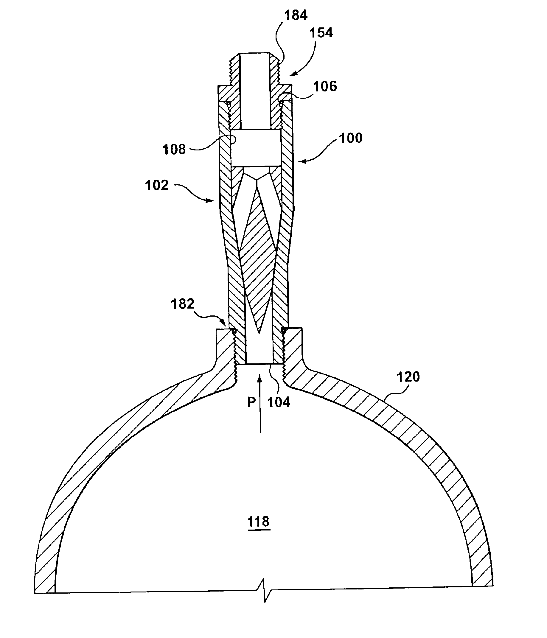
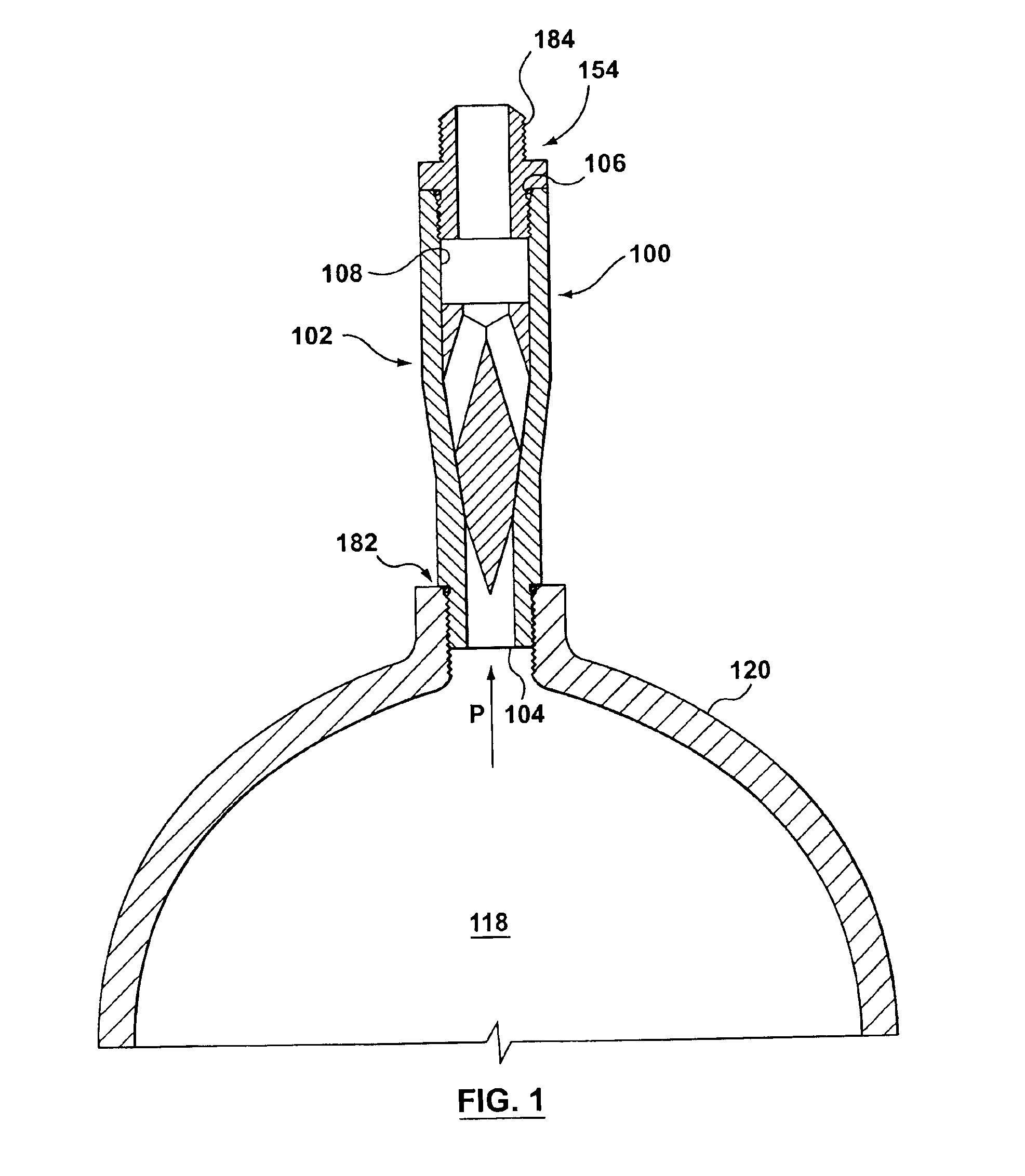
A pressure relief device having a housing including an inlet, an outlet, and an inner wall defining a bore connecting the inlet and the outlet. The inlet is in communication with a fluid under pressure in a pressure vessel. The bore includes an inlet portion extending from the inlet toward the outlet, and an outlet portion extending from the outlet toward the inlet. The bore also includes a tapered portion connecting the inlet portion and the outlet portion. The inlet portion has a diameter which is less than the outlet portion's diameter. A plug is located in the bore and movable from a closed position, in which flow of fluid through the bore is blocked, to an open position, in which flow of the fluid through the bore is permitted in response to a pressure differential between the inlet and the outlet.

Description

FIELD OF THE INVENTIONThis invention relates to pressure relief devices for relieving pressure on a fluid in a pressure vessel.BACKGROUND OF THE INVENTIONPressure relief devices for use with fluids held under pressure in various pressure vessels are known. Typically, a pressure relief device includes a plug positioned in a passage within a housing attached to a pressure vessel, with the plug normally in a closed position. An inlet of the passage is in communication with the fluid in the pressure vessel when the plug is closed. In a conventional pressure relief device, the plug blocks the flow of the fluid through the passage when the plug is in the closed position, and the plug is movable to an open position in which the fluid can exit the pressure vessel via the passage.The conventional pressure relief device is intended to relieve excess pressure to which the fluid in a pressure vessel is subjected or, alternatively, to release the fluid in the event of fire. Such excess pressure ...

Claims


Application Information

Patent Timeline
IPC IPC(8): F16K17/38F16K17/04F16K17/36F16K17/08
CPCF16K17/0466F16K17/383F16K17/08Y10T137/1963Y10T137/1812
Inventor GIROUARD, ERICK
Owner WESTPORT FUEL SYST CANADA INC
Why Eureka
Try Eureka