Steering-wheel revolution number correction system of all-wheel-drive vehicle

a technology of all-wheel drive and revolution number, which is applied in the direction of steering linkage, non-deflectable wheel steering, transportation and packaging, etc., can solve the problem that the inner race difference between the front and rear wheels during the turning movement cannot be completely absorbed, the vehicle cannot turn smoothly, and the tight-corner braking phenomenon cannot be securely prevented. the effect of restrainting the tight-corner braking phenomenon

Inactive Publication Date: 2005-02-22
KOMATSU LTD
View PDF17 Cites 89 Cited by
  • Summary
  • Abstract
  • Description
  • Claims
  • Application Information

AI Technical Summary

Benefits of technology

In the present invention, following arrangement is used for a steering-wheel revolution number correction system of an all-wheel-drive vehicle for easily and accurately controlling the revolution number of the front-wheel while turning the vehicle and securely preventing the tight-corner braking phenomenon even when the vehicle has an articulating type frame.
However, according to the present invention, because the revolution number of the hydraulic motor for driving the front-wheel is directly controlled, low-torque and high-speed drive can be achieved with small flow rate of delivery oil even when the flow rate of the delivery oil of the hydraulic pump is small, so that the revolution number of the hydraulic motor can be maintained at a high-speed rotation and the tight-corner braking phenomenon can be restrained.

Problems solved by technology

However, in a vehicle having an all-wheel-drive where the front-wheel rotates in synchronization with the rotation of the rear-wheel, the rotation difference of the front and rear wheels caused by the inner race difference during turning movement cannot be completely absorbed, so that the vehicle turns with the front-wheel being braked.
Accordingly, unless the front-wheel is rotated faster than the rear-wheel, a so-called “tight-corner” braking phenomenon occurs during turning movement and the vehicle does not turn smoothly.
However, according to the disclosure of the U.S. Pat. No. 4,186,816, because the front-wheel always rotates faster than the rear-wheel by a predetermined ratio, a problem occurs when the vehicle turns at the same speed (the same revolution number of the rear-wheel) and with different turning radius.
Specifically, though the front-wheel has to be rotated faster as the turning radius becomes smaller, since the revolution number of the front-wheel is determined irrespective of the turning radius, the front-wheel does not rotate at a revolution number corresponding to the turning radius, so that the tight-corner braking phenomenon cannot be securely prevented.
Further, the rotation of the front-wheel faster than the rear-wheel by the several percent cannot rotate the front-wheel sufficiently fast when the vehicle turns with a small turning radius.
Because the slippage of the rear-wheel is required in the technique shown in U.S. Pat. No. 5,147,010, the front-wheel does not rotate fast when the vehicle is turned and the rear-wheel does not always slip, so that the tight-corner braking phenomenon cannot be securely prevented.
Further, because only the hydraulic pressure to the hydraulic motor is monitored in this technique, when the ground pressure of the front-wheel is decreased and is likely to be slipped when, for instance, the work is conducted while keeping the blade in contact with the ground, the hydraulic motor may be rotated at a high speed without sufficient hydraulic pressure and the front-wheel may keep on slipping.
The energy is wasted in the above condition.
However, it is so troublesome to operate the auxiliary lever throughout turning the vehicle in addition to steering operation.
Further, it takes considerable skill and is not easy to properly adjust the revolution number of the front-wheel in accordance with the speed of the vehicle and the turning radius.
However, in an articulating motor grader having the front-wheel and the rear-wheel attached to independent frames, the respective frames being angle-adjustably connected, because the turning radius on the front-wheel side greatly changes relative to the rear-wheel side not only by the steering operation but by articulating the front frame on the front-wheel side relative to the rear frame on the rear-wheel side, accurate turning radius cannot be obtained only by detecting the steering angle.

Method used


Image

  • Steering-wheel revolution number correction system of all-wheel-drive vehicle
  • Steering-wheel revolution number correction system of all-wheel-drive vehicle
  • Steering-wheel revolution number correction system of all-wheel-drive vehicle

Examples


first embodiment

[First Embodiment]

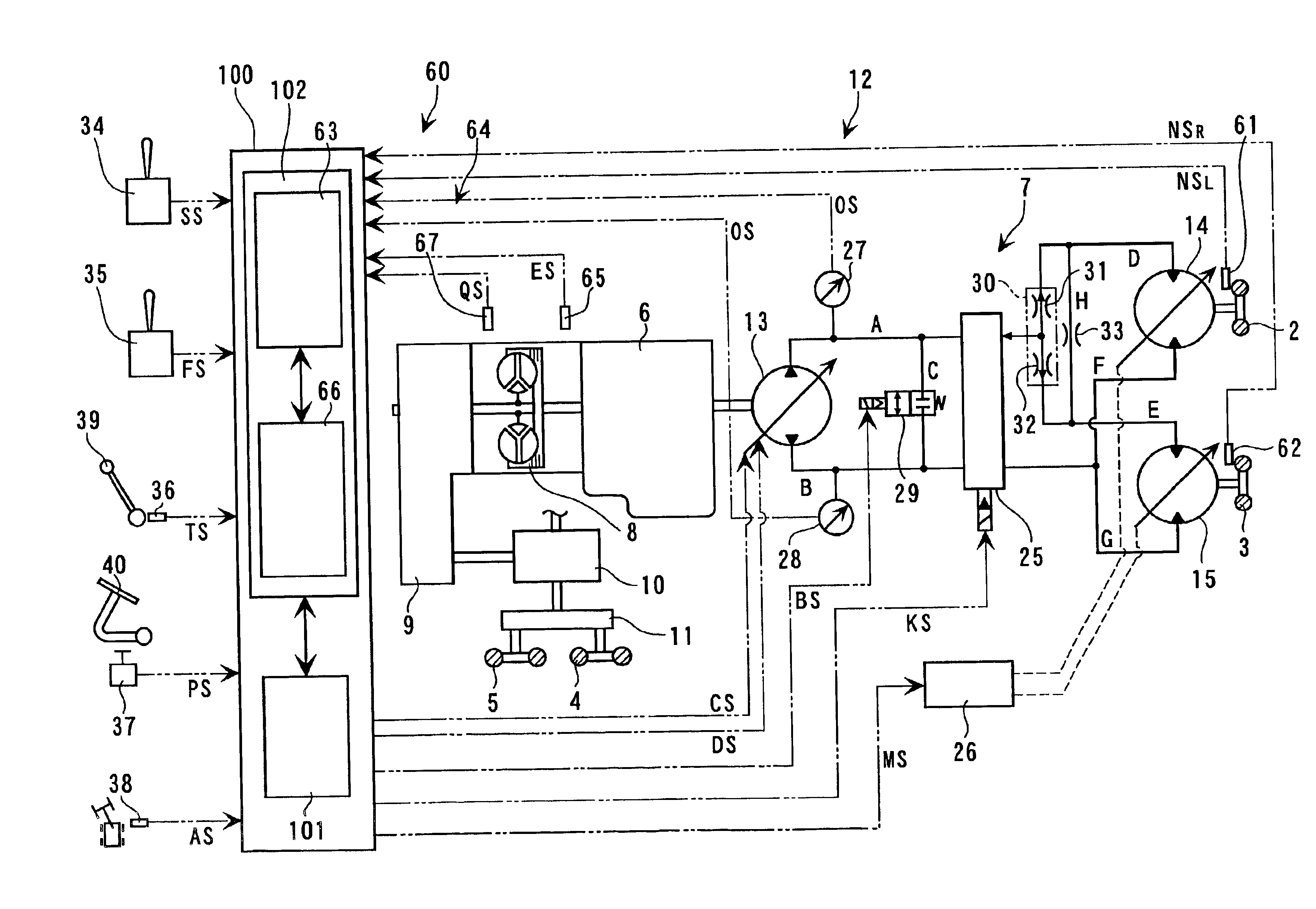
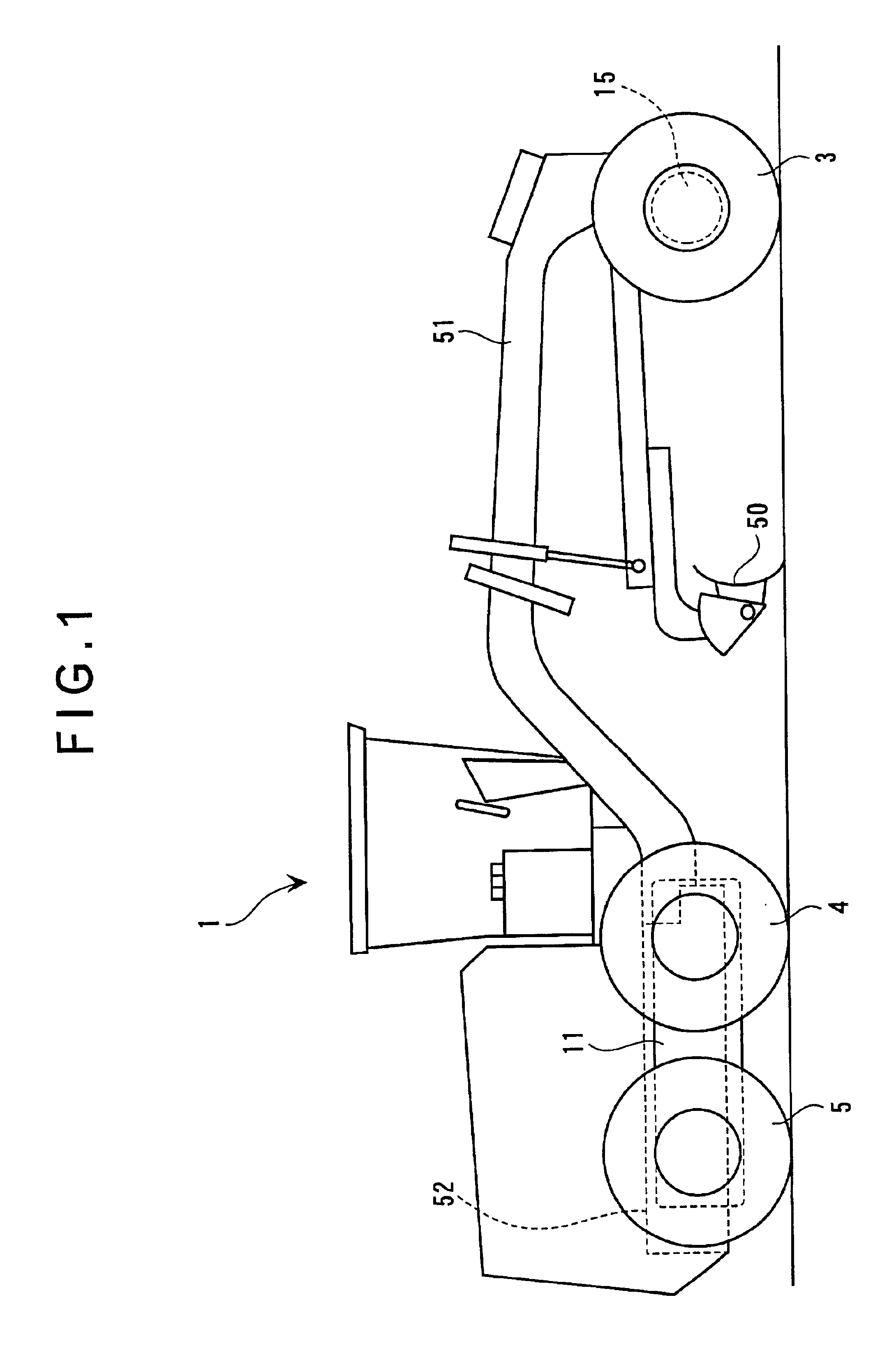
FIGS. 1 to 5 show a motor grader 1 as an all-wheel-drive vehicle according to first embodiment of the present invention applied with the steering-wheel revolution number correction system of the present invention.

In FIGS. 1 and 2, the motor grader 1 is a vehicle having total six wheels, i.e., a pair of front wheels of a left front-wheel 2 and right front-wheel 3, and rear-wheels which are provided in pairs on both sides, the rear-wheels including left rear-front wheel and left rear-rear wheel (not shown) and a right rear-front wheel 4 and a right rear-rear wheel 5, where a blade 50 provided between the front-wheels 2 and 3 and the rear-wheels 4 and 5 levels the ground, removes snow, cuts with low load and mixes material, etc.

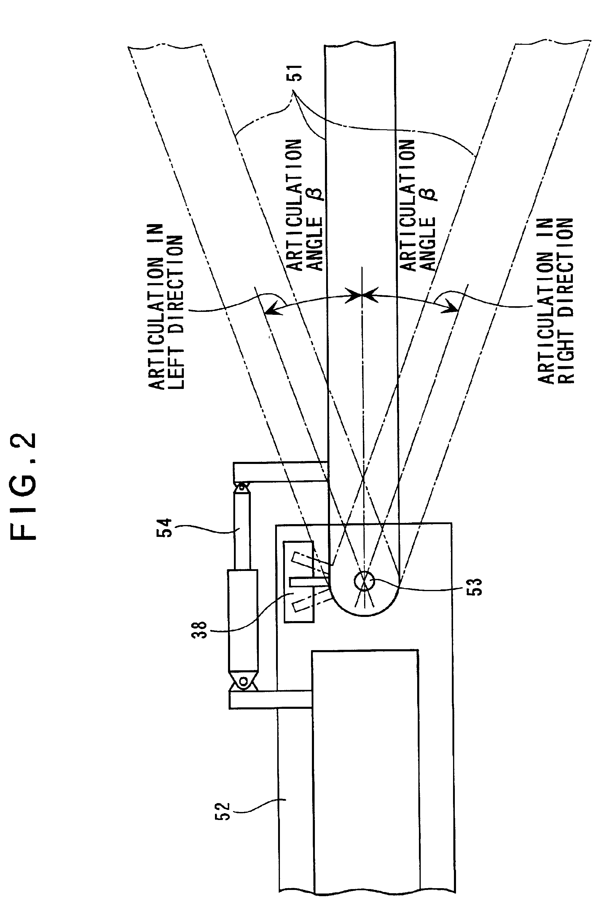
The front-wheels 2 and 3 as well as the blade 50 are mounted on a front frame 51 and the rear-wheels 4 and 5 are mounted on the rear frame 52. As shown in FIG. 2, the front frame 51 is rotatably connected to the rear frame 52 by a vertical cent...

second embodiment

[Second Embodiment]

Next, a second embodiment of the present invention will be described below.

The second embodiment includes a steering-wheel revolution number correction system 160 instead of the steering-wheel revolution number correction system 60 of the first embodiment. Accordingly, the description for common components will be omitted and the description will be concentrated on the steering-wheel revolution number correction system 160 as a different component.

In FIG. 10, the steering-wheel revolution number correction system 160 includes a left pickup sensor 161 as a steering-wheel revolution number detecting means for detecting the revolution number of the left front-wheel 2, a right pickup sensor 162 as another steering-wheel revolution number detecting means for detecting the revolution number of the right front-wheel 3, a turning radius operation 163 for determining the turning radius of the front-wheels 2 and 3 based on the revolution number of the front wheels 2 and 3, ...


PUM


Abstract

Turning radius is calculated from steering angles of steering-wheels and articulation angles of respective frames, and the steering-wheels are automatically rotated faster than rear-wheels based on the turning radius, the revolution number of the rear-wheels, engine speed of an engine and a speed range of hydraulic motors, so that conventional trouble for manipulating operation lever etc. while turning a motor grader and skill-requiring work for adjusting the revolution number of the steering-wheels in accordance with the revolution number of the rear-wheels can be eliminated, thereby easily and accurately controlling the revolution number of the steering-wheels and securely preventing tight-corner braking phenomenon.

Description

BACKGROUND OF THE INVENTION1. Field of the InventionThe present invention relates to a steering-wheel revolution number correction system of all-wheel-drive vehicle. More specifically, it relates to a steering-wheel revolution number correction system of a construction equipment provided with an all-wheel-drive, such as a motor grader and a wheel loader.2. Description of Related ArtRecently, all-wheel-drive for driving all of front and rear wheels is often provided to a motor grader, etc.The all-wheel drive drives the rear-wheel by an output of an engine transmitted through a transmission and the output of the engine is transmitted to a hydraulic pump, where right and left front-wheels are driven by a pair of hydraulic motors rotated by delivery oil from the hydraulic pump.Incidentally, when the vehicle turns, because the turning radius of the front-wheel becomes greater than the turning radius of the rear-wheel on account of inner race difference, the front-wheel has to be rotated ...

Claims


Application Information

Patent Timeline
Patent Type & Authority Patents(United States)
IPC IPC(8): B62D9/00B62D12/00
CPCB62D12/00B62D9/002
Inventor KOBAYASHI, TETSUONISHIMAKI, KAZUHITO
Owner KOMATSU LTD
Why Eureka
Try Eureka