Device for loading a shaft furnace

a technology for loading devices and shaft furnaces, which is applied in vertical furnaces, furnaces, lighting and heating apparatuses, etc., can solve problems such as inaccuracy of rotor centering, and achieve the effect of easy replacement and easy integration

US6857872B2Inactive Publication Date: 2005-02-22PAUL WURTH SA
6 Cites 3 Cited by

Patent Information

Authority / Receiving Office
US · United States
Patent Type
Patents(United States)
Current Assignee / Owner
Publication Date
2005-02-22
Estimated Expiration
Not applicable · inactive patent

Smart Images

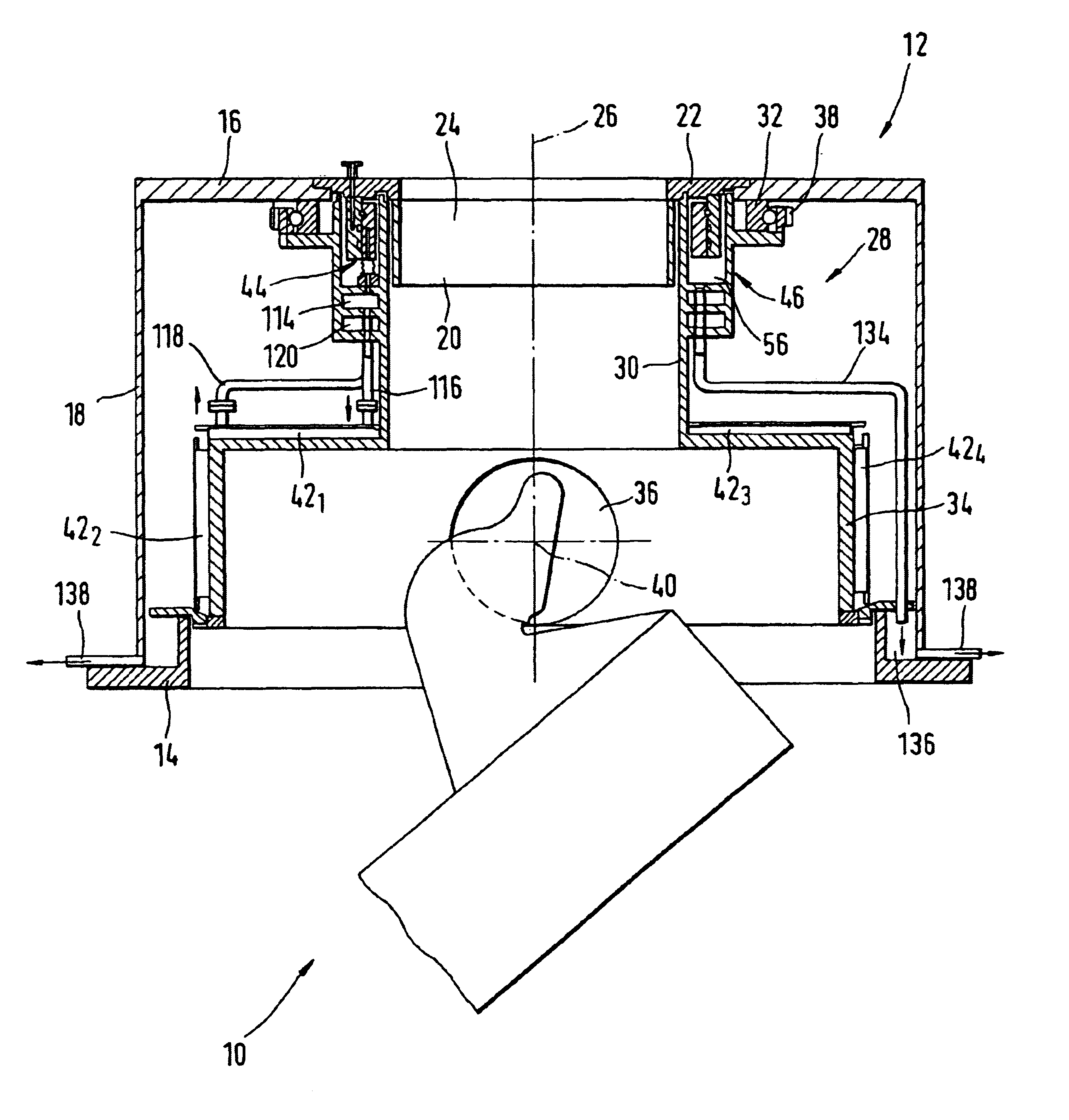
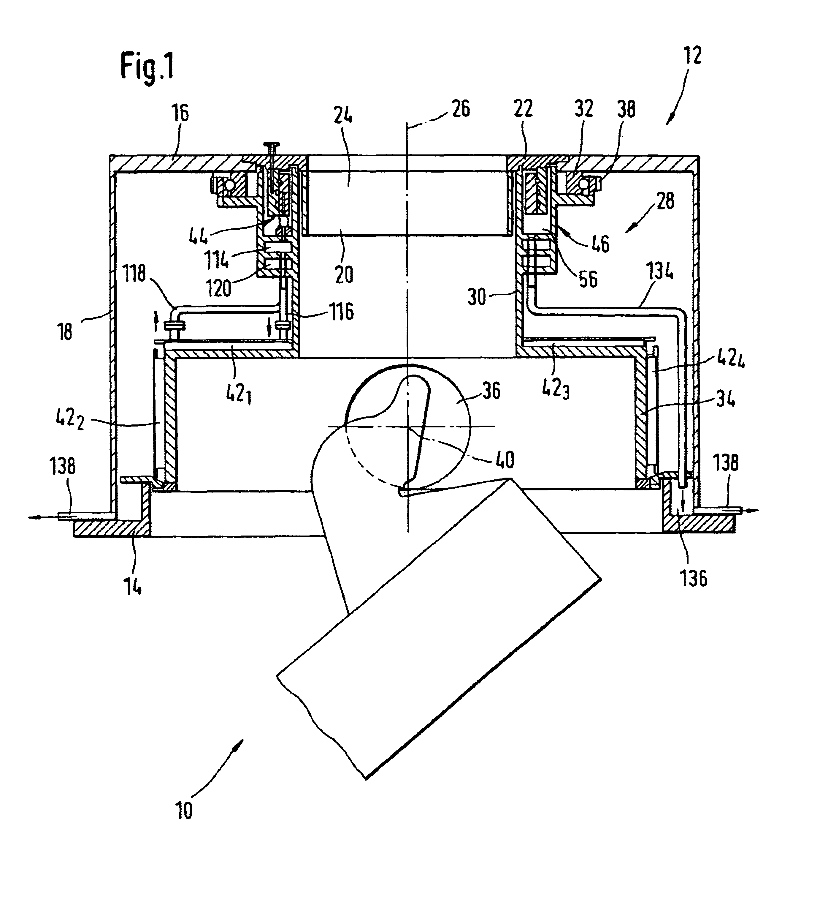
  • Figure 1
    Figure 1
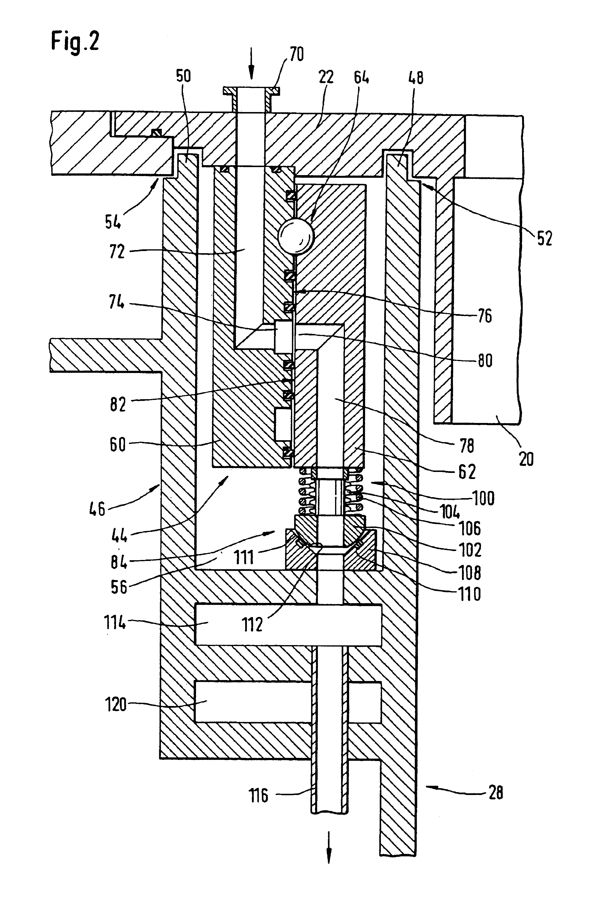
  • Figure 2
    Figure 2
  • Figure 3
    Figure 3
Patent Text Reader

Abstract

A loading device for a shaft furnace comprises a chute supported by a suspension rotor (28) in a fixed housing. The rotor (28) is fitted with a cooling circuit, supplied with liquid coolant via a rotating annular joint (44). The latter comprises a fixed ring (60) and a rotating ring (62), and is fitted in an annular leak collecting tank (46) formed by the suspension rotor (28). Fixed ring (60) is supported by the housing (12). Rotating ring (62) is supported entirely by fixed ring (60) via a bearing (64). Selective coupling means (65, 66) connect the rotating ring (62) to the suspension rotor (28) in such a way as to transmit a rotary moment of rotor (28) to rotating ring (62) selectively, while at the same time preventing other forces from rotor (28) being transmitted to rotating ring (62).
Need to check novelty before this filing date? Find Prior Art

Description

FIELD OF THE INVENTIONThe present invention concerns a loading device for a shaft furnace. More particularly, it concerns the cooling of a loading device for a shaft furnace, such as a blast furnace, comprising a housing to be mounted at the top of the shaft furnace, a suspension rotor suspended in such a way that it rotates on that housing, a loading chute suspended in the suspension rotor and at least one cooling circuit supported by the suspension rotor.BACKGROUND OF THE INVENTIONIn 1978, the company Paul Wurth S. A. proposed such a loading device, which is described in detail in U.S. Pat. No. 4,273,492. The suspension rotor in this device is fitted with a lower protective screen which surrounds the chute feed channel and protects the drive means mounted in the housing against the radiant heat from the inside of the shaft furnace in particular. To this end, the lower screen contains a cooling circuit which is supplied with liquid coolant via a rotating annular connection around t...

Examples

Embodiment Construction

In the figures shown, item numbers which are the same indicate components which are similar or identical.

FIG. 1 shows a loading device with a rotating chute 10, designed to be mounted on a shaft furnace, such as a blast furnace, in diagrammatic form.

This device consists of a housing 12 with an annular flange 14 at the bottom, a support plate 16 at the top and a side wall 18. The annular flange 14 connects the housing 12 to a mating flange (not shown) of a shaft furnace, to produce a watertight joint. The support plate 16 is connected to the bottom of a hopper or gate housing (not shown). Side wall 18 provides a watertight connection between flange 14 and supporting plate 16. A fixed feed sleeve 20 is mounted in a central opening of the support plate 16 by means of an annular flange 22. This fixed feed sleeve 20 extends into housing 12 to define a feed channel 24 for the material to be loaded into the shaft furnace. This feed channel 24 has a central axis 26 which is normally coincid...