Computer enclosure with slidably mounted drive bracket

a technology of drive brackets and computer enclosures, which is applied in the direction of ventilation systems, electrical apparatus casings/cabinets/drawers, instruments, etc., can solve the problems of cumbersome and time-consuming operations, unduly inconvenient and time-consuming, and achieve the effect of convenient assembly and convenient assembly

Inactive Publication Date: 2005-02-22
HON HAI PRECISION IND CO LTD
View PDF10 Cites 2 Cited by
  • Summary
  • Abstract
  • Description
  • Claims
  • Application Information

AI Technical Summary

Benefits of technology

Accordingly, an object of the present invention is to provide a computer enclosure which is readily and conveniently assembled.

Problems solved by technology

However, it is not easy to detach the drive cages and the motherboard support tray from the case.
In such instances, the operations are cumbersome and time-consuming, especially because of limited space in the enclosure.
This is unduly inconvenient and time-consuming.
In mass production facilities, these difficulties translate into increased costs.

Method used


Image

  • Computer enclosure with slidably mounted drive bracket
  • Computer enclosure with slidably mounted drive bracket
  • Computer enclosure with slidably mounted drive bracket

Examples


Embodiment Construction

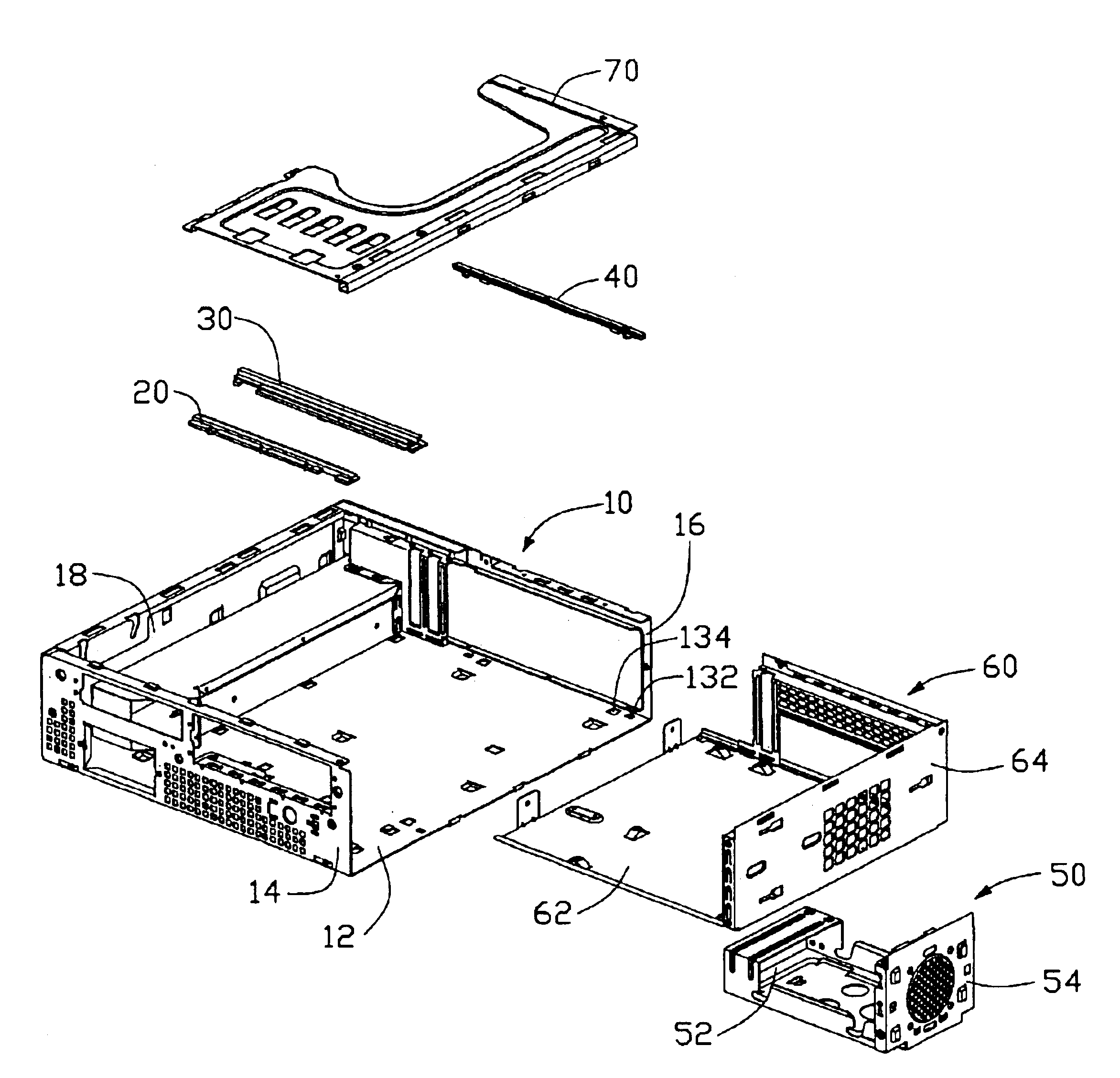
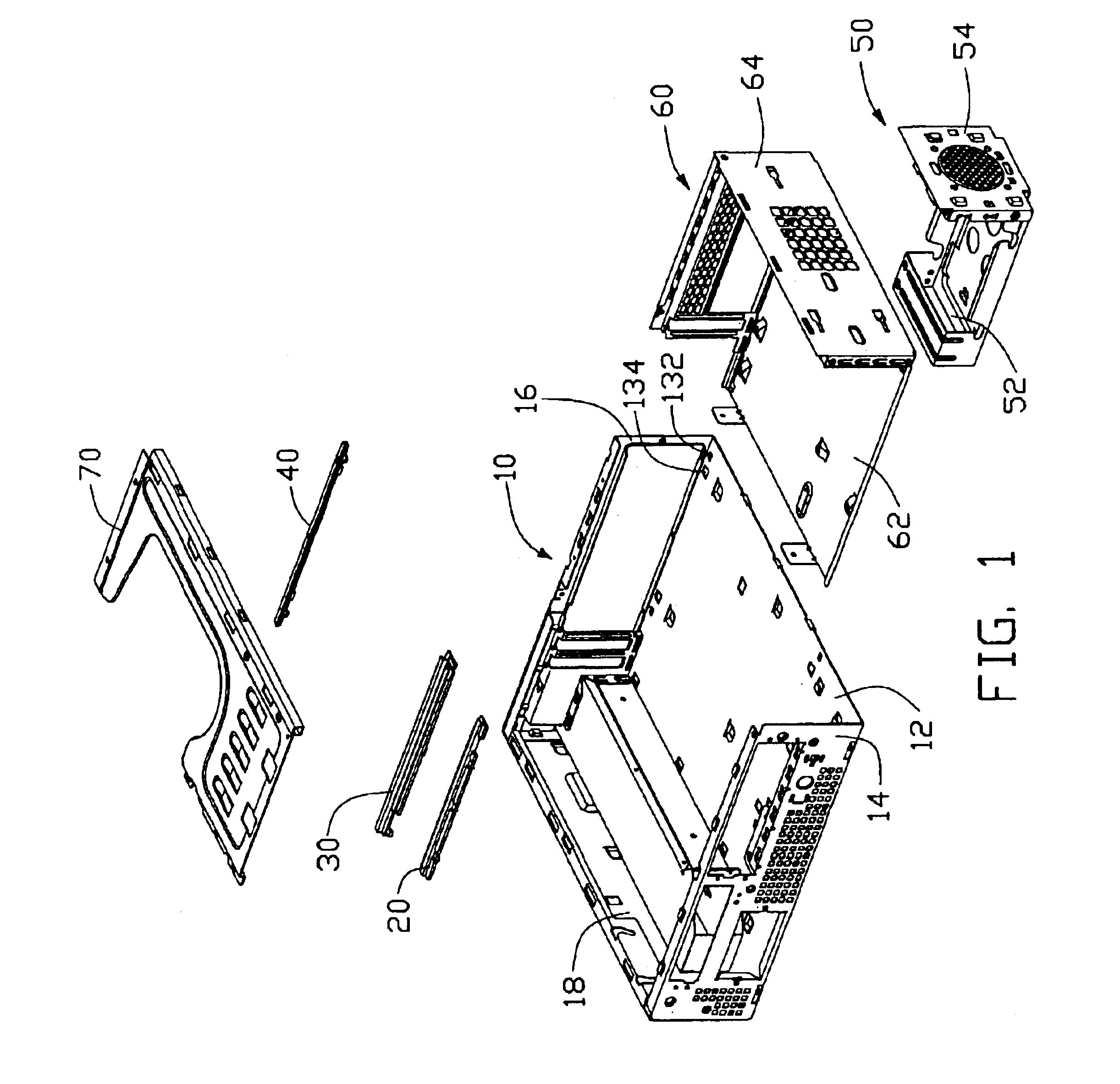
Referring to FIG. 1, a computer enclosure in accordance with the present invention comprises a case 10, a first rail 20, a second rail 30, a third rail 40, a drive bracket 50, a motherboard support tray 60 and a reinforcing plate 70.

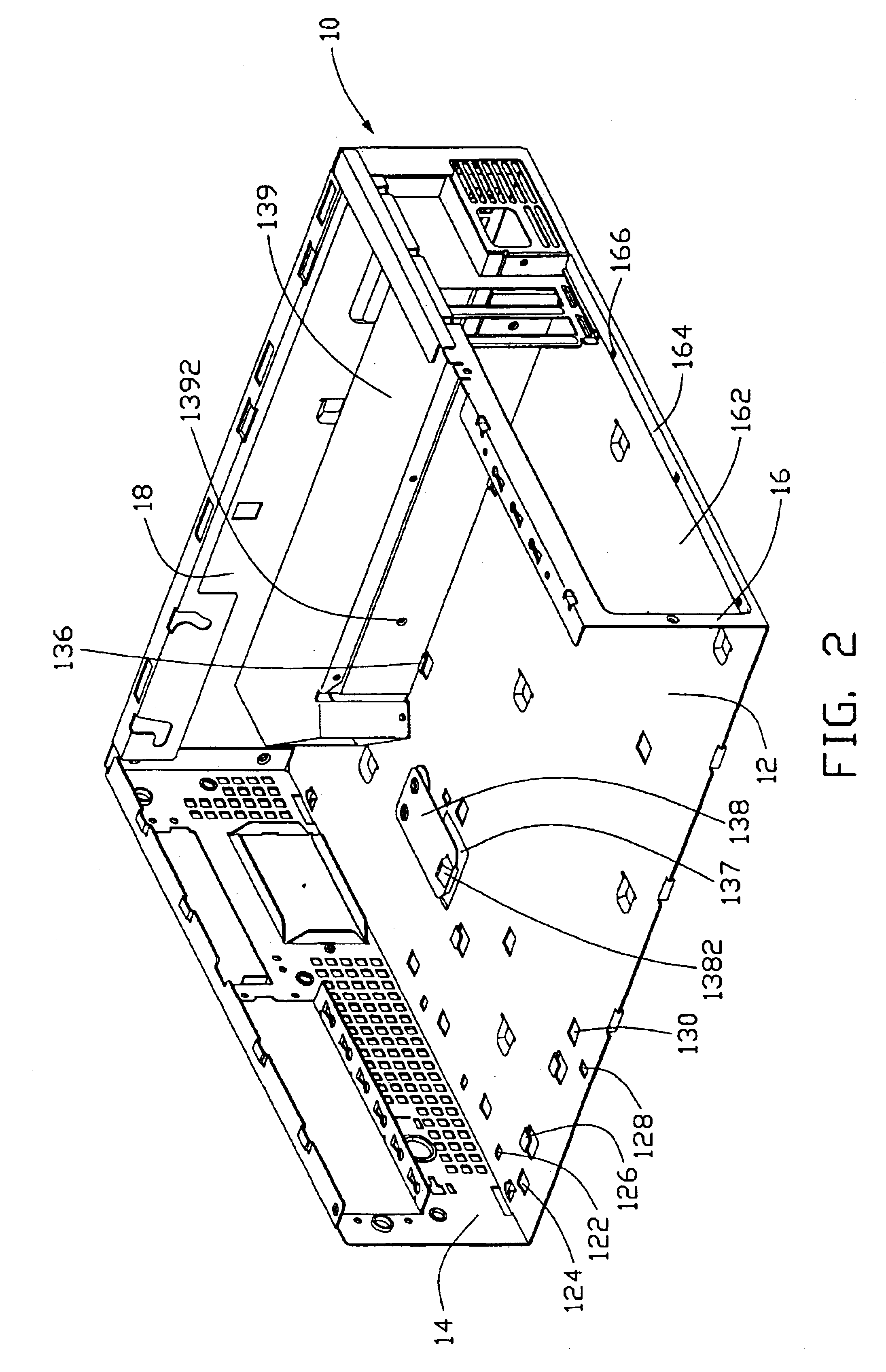
Referring also to FIG. 2, the case 10 comprises a bottom wall 12, a front wall 14 and a rear wall 16 perpendicularly extending from two opposite sides of the bottom wall 12 respectively, a first sidewall 18 extending from the bottom wall 12, and an opening defined at a side of the case 10 that is opposite from the first sidewall 18. Three aligned first square holes 122 are defined in the bottom wall 12, close and parallel to the front wall 14. Four aligned first trapezoidal holes 124 are defined in the bottom wall 12, close and parallel to the front wall 14. The first trapezoidal holes 124 are more distant from the front wall 14 than the first square holes 122. Three L-shaped first hooks 126 are upwardly formed from the bottom wall 12, at a side of the f...


PUM


Abstract

A computer enclosure includes a case (10), a first rail (20), a second rail (30), a third rail (40), a drive bracket (50) and a motherboard support tray (60). The case includes a bottom wall (12), a front wall (14), and a rear wall (16). The first rail is mounted to a side portion of the bottom wall that is parallel and close to the front wall. The second rail is mounted to the bottom wall, the second rail being spaced from and parallel to the first rail. The third rail is mounted to a side portion of the bottom wall that is parallel and close to the rear wall. The drive bracket is slid between the first and second rails, and is thus removably mounted in the case. The motherboard support tray is slid between the second and third rails, and is thus removably mounted in the case.

Description

BACKGROUND OF THE INVENTION1. Field of the InventionThe present invention relates to computer enclosures with slidably mounted drive brackets, and particularly to a computer enclosure which is readily and conveniently assembled.2. Related ArtA conventional computer enclosure comprises a case that is typically in the form of a rectangular frame, and comprises a bottom wall, a top wall, a front wall and a rear wall. The case encloses components such as a floppy drive, a hard drive, a CD-drive, and so on. Drive cages and a motherboard support tray are also arranged in the case. The drive cages and the motherboard support tray are secured in the case by hooks or screws. Typical such computer enclosures are disclosed in Taiwan Patent Publications Nos. 414421 and 417800. However, it is not easy to detach the drive cages and the motherboard support tray from the case. For example, drives in the drive cages or electronic components on the motherboard may need to be tested or replaced. Becau...

Claims


Application Information

Patent Timeline
Patent Type & Authority Patents(United States)
IPC IPC(8): G06F1/18
CPCG06F1/184
Inventor LIU, ALVIN
Owner HON HAI PRECISION IND CO LTD
Why Eureka
Try Eureka