Lockable pushbutton actuator for a display device such as a watch

Active Publication Date: 2005-03-29
SEIKO EPSON CORP
View PDF7 Cites 29 Cited by
  • Summary
  • Abstract
  • Description
  • Claims
  • Application Information

AI Technical Summary

Benefits of technology

An object of the present invention is to provide a button that allows the design of t

Problems solved by technology

The fixed member is fixed to the base, and supports the lock member in a manner that allows rela

Method used


Image

  • Lockable pushbutton actuator for a display device such as a watch
  • Lockable pushbutton actuator for a display device such as a watch
  • Lockable pushbutton actuator for a display device such as a watch

Examples


first embodiment

(First Embodiment)

The button structure related to the first embodiment of the present invention is described below based on FIGS. 1 to 4.

The button structure of the present embodiment is one of an operating button 10 disposed on a external surface of a main body of a wristwatch, pocket watch, or other portable watch; or a stopwatch, dive computer, or other type of portable equipment.

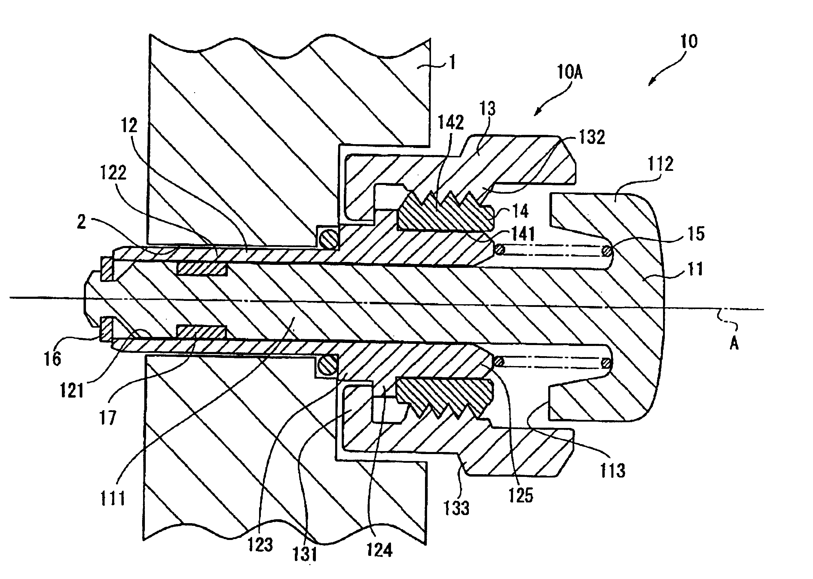
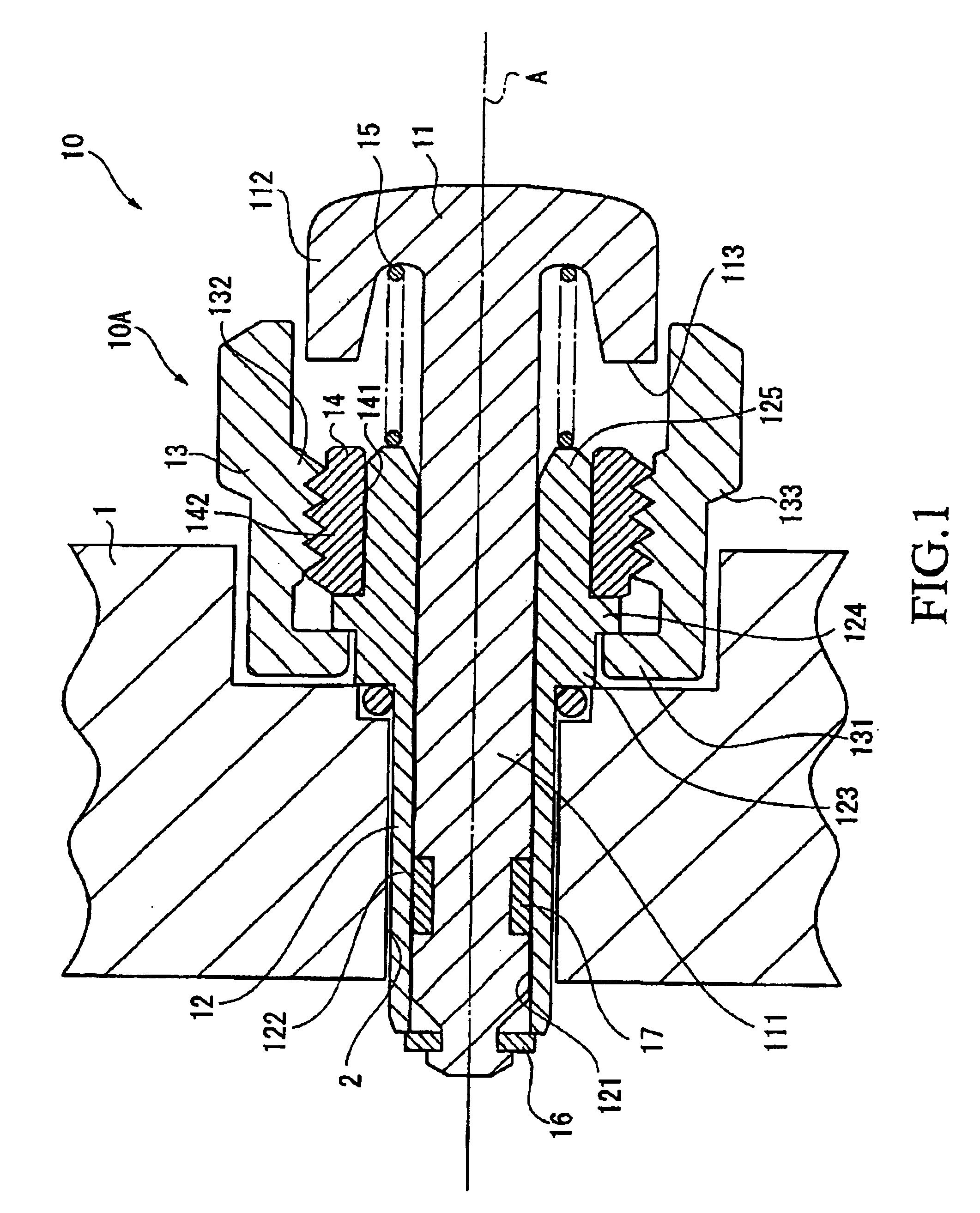
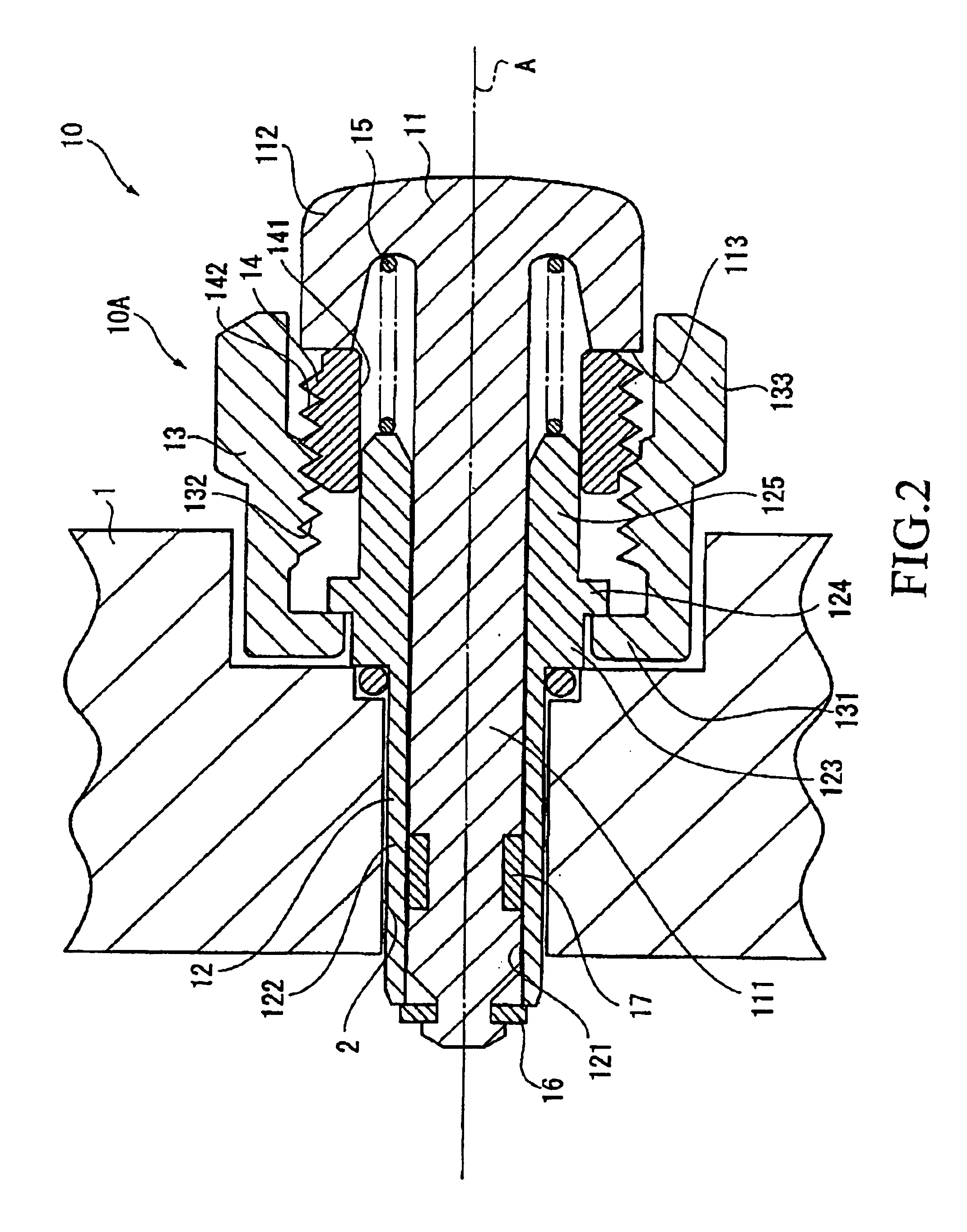
FIGS. 1 and 2 show the operating button 10 and are cross-sectional views that illustrate the unlocked and locked states, respectively. FIG. 3 is an exploded perspective view of the operating button 10. FIG. 4 is a side view showing the essential portions of the operating button 10, and is a side view of a hereinafter-described fixed member 12.

In FIGS. 1 to 4, a case 1 serving as the casing forms the external shell of portable equipment (the main body of the portable equipment), and houses drive mechanisms, power sources, computing units, display units, and other components (not depicted). The operating b...

second embodiment

(Second Embodiment)

Next, the button structure related to the second embodiment of the present invention is described based on FIGS. 5 to 7.

The button structure of the present invention has substantially the same configuration as the operating button 10 in the above-described first embodiment, but differs in that the shape of the lock member 14 is different and a restricting member is provided. These differences are described in detail below.

FIG. 5 is a cross-sectional view showing the operating button 10 of the present embodiment, the area above the axial center A shows a locked state, and the area below the axial center A shows an unlocked state.

In FIG. 5, the lock member 14 protrudes toward the head portion 112 of the button member 11, and has a locked state indicator 145 formed in the shape of a ring about axial center A. When locked, a locked state indicator 145 protrudes by an amount equal to the dimension x away (right side of the diagram) from the gap between the head portion...

third embodiment

(Third Embodiment)

Next, the button structure related to the third embodiment of the present invention is described based on FIGS. 8 and 9.

The button structure of the present invention has substantially the same configuration as the operating button 10 in the above-described first embodiment, but differs in terms of the threading and connecting relationships of the fixed member 12, the ring member 13, and the lock member 14. These differences are described in detail below.

FIGS. 8 and 9 are-cross-sectional views showing the operating button 10 and the unlocked and locked states, respectively.

In FIGS. 8 and 9, a guide portion 125 of the fixed member 12 is formed into a shape whose cross section is substantially cylindrical, and a threaded portion 126 that threadably engages the internal peripheral surface of the lock member 14 is formed on the external peripheral surface of the guide portion 125. A guide groove 134 that slidably engages the external peripheral surface of the lock membe...


PUM


Abstract

There is provided a button capable of entry and exit with respect to a base. The button has a button member, ring member, lock member, and fixed member. The button member has a shaft portion mounted in a manner that allows entry and exit with respect to the base, and an expanded-diameter portion with a shaft diameter that is larger than the diameter of the shaft portion. The ring member accommodates the shaft portion and can rotate about the axial center of the shaft portion. The lock member moves along the axial center between the ring member and the shaft portion due to the rotation of the ring member, and restricts the entry and exit action of the button member by coming into contact with the expanded-diameter portion of the button member. The fixed member is fixed to the base and stops the ring member to restrict the movement of the ring member along the axial center.

Description

BACKGROUND OF THE INVENTION1. Field of the InventionThe present invention relates to a button and to portable equipment provided therewith, and more particularly to a button suitable to be installed in watches and other portable equipment.2. Description of the Related ArtOperating buttons are commonly disposed on the external surface of a main body of a wristwatch, pocket watch, or other portable watch; or a stopwatch, dive computer, or other type of portable equipment. In such an operating button, the button member is normally mounted to protrude slightly from the external surface of the main body in a manner that allows entry and exit with respect to the base, and is configured so that the contact or the like within the main body operates by pressing this button member. Also, a lock mechanism for restricting the thrust action of the button member has been proposed for preventing operating button malfunctions (JP-A 2003-7164).The operating button with a lock mechanism cited in JP-A...

Claims


Application Information

Patent Timeline
IPC IPC(8): G04B3/00G04B3/04G04B37/00G04B37/10G04G21/00H01H3/20H01H13/02H01H13/14
CPCG04B37/106G04B3/048
Inventor OSHIO, TAKUMILAM, KOWK FAI
Owner SEIKO EPSON CORP
Why Eureka
Try Eureka