Relief valve

a technology of pressure relief valve and valve body, which is applied in the direction of valve operating means/releasing devices, functional valve types, transportation and packaging, etc., can solve the problems of affecting the durability of conventional relief valves, prone to chattering problems, and incurring chattering problems

Inactive Publication Date: 2005-04-05
SURPASS IND
View PDF4 Cites 1 Cited by
  • Summary
  • Abstract
  • Description
  • Claims
  • Application Information

AI Technical Summary

Benefits of technology

Under such circumstances, the present invention was made to solve the problems inherent in the prior art. Consequently, it is an object o

Problems solved by technology

Due to this, the conventional relief valve tends to incur the chattering problem.
Consequently, this incurs the chattering problem of the valve element 37 of the con

Method used


Image

  • Relief valve
  • Relief valve
  • Relief valve

Examples


Embodiment Construction

The best modes for carrying out the present invention will be described in detail using embodiments of the present invention with reference to the accompanying drawings.

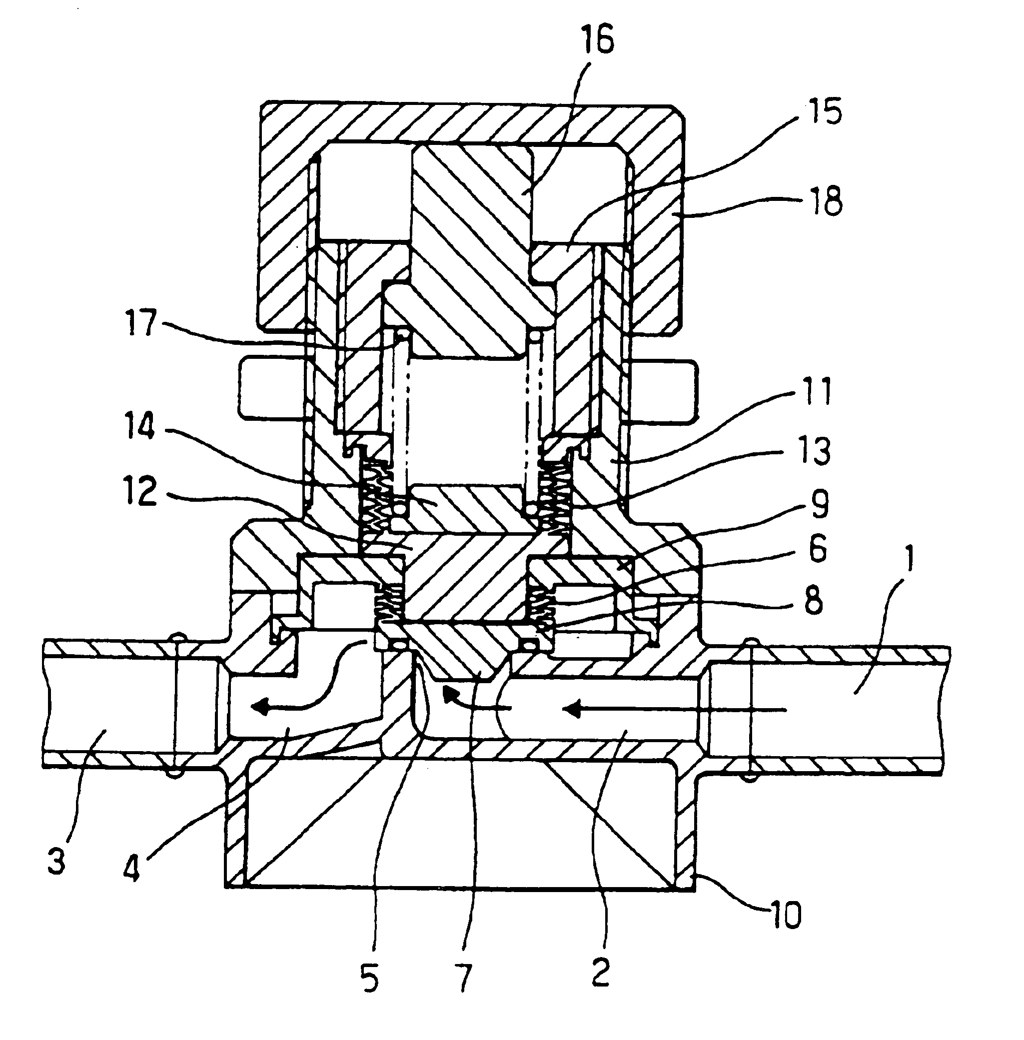
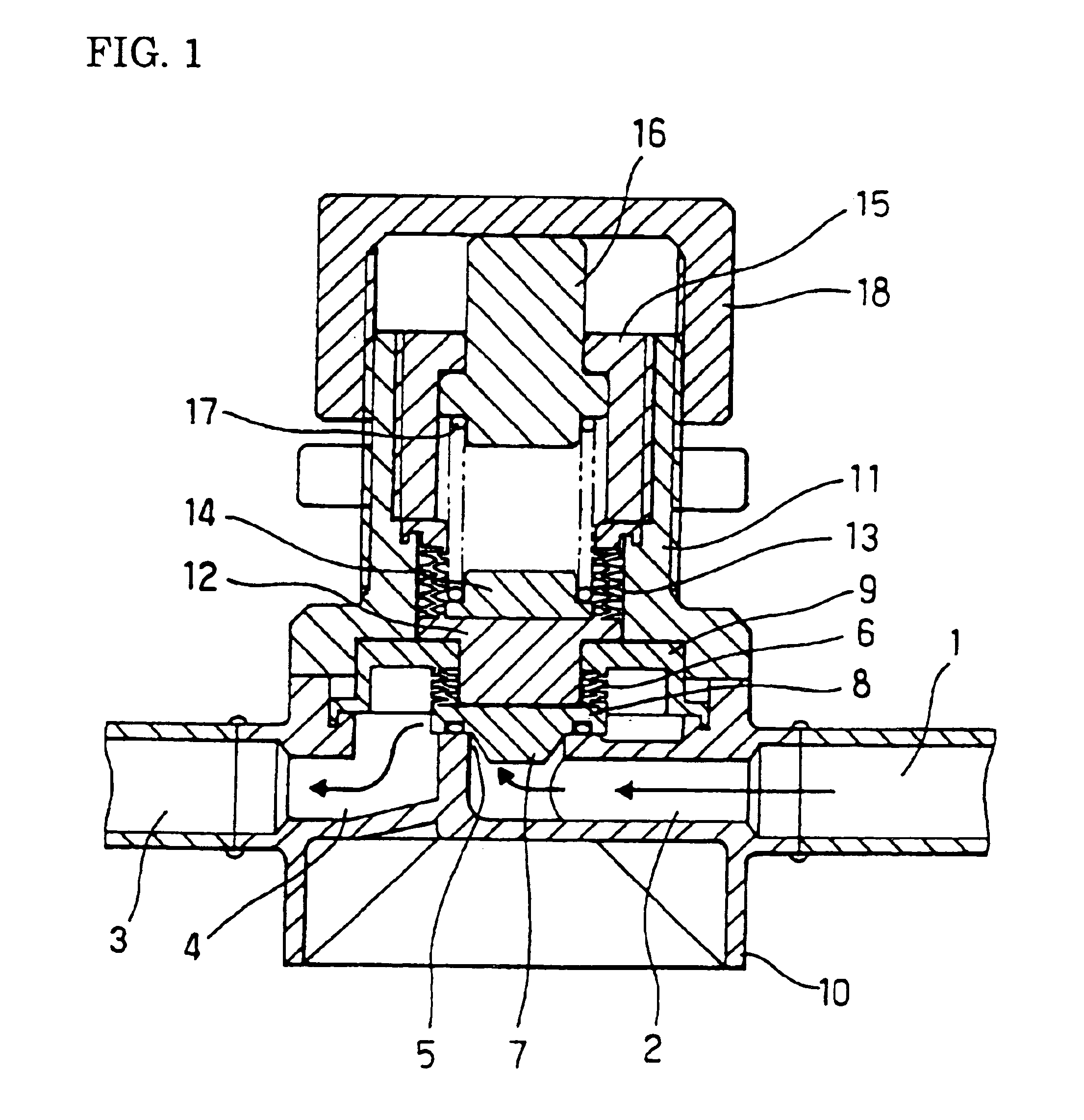
FIG. 1 shows a longitudinal sectional view of an embodiment of a pressure relief valve of the present invention.

As is clear from FIG. 1, is a pressure relief valve of the present invention includes a valve body 10, which defines a relief fluid passage 5.

Further include in the relief valve is a valve element 7, which is adapted to open and close the relief fluid passage 5. The valve element 7 is disposed between an inlet port 2 and an outlet port 4. The inlet port 2 is directed upward in the valve body 10 and is in direct communication with an upstream-side fluid passage 1. On the other hand, the outlet port 4 is directed downward in the valve body 10 and is in direct communication with a downstream-side fluid passage 3.

The valve element 7 is provided with a flange portion 8 in its upper portion.

Still further included...


PUM


Abstract

In a conventional relief valve having a valve element supported by a diaphragm, since a surface of the valve element exposed to pressure is large and an opening/closing operation of the valve element is rapidly conducted, the operation often leads to chattering and is therefore poor in stability. A relief valve of the invention is free from chattering and capable of smoothly performing the opening/closing operation of its valve element (7). The element (7) is adapted to open and close a fluid passage and disposed between: an inlet port (2) in direct communication with an upstream-side fluid passage (1); and, an outlet port (4) in direct communication with a downstream-side fluid passage (3), and is provided with a flange (8) in its upper portion. Mounted on the flange (8) is a sleeve-like bellows (6) for supporting the valve element (7).

Description

BACKGROUND OF THE INVENTION1. Field of the InventionThe present invention relates to a pressure relief valve, and more particularly to a pressure relief valve fitted to a fluid distribution system to control fluid in pressure in the system.2. Description of the Related ArtIn general, as shown in FIG. 2, a pressure relief valve of a conventional type comprises; an inlet port 32 in direct communication with an upstream-side flow passage 31; and, an outlet port 34 in direct communication with a downstream-side flow passage 33. In the conventional relief valve having the above construction, a relief fluid passage 35 intermediate the inlet port 32 and the outlet port 34 is opened and closed by a valve element 37, which has its peripheral portion supported by a resilient diaphragm 36.As is clear from FIG. 2, the valve element 37 is always pushed downward by the spring 38 so that the relief fluid passage 35 normally stays closed. However, when a fluid pressure in the inlet port 32 reaches ...

Claims


Application Information

Patent Timeline
IPC IPC(8): F16K17/04F16K47/02
CPCF16K17/0433Y10T137/7929Y10T137/7923Y10T137/7738F16K15/063F16K15/026F16K2200/302
Inventor IGARASHI, HIROKI
Owner SURPASS IND
Why Eureka
Try Eureka